


C1644M-B (6/06) 13
MOUNTING THE TRANSMITTER/RECEIVER TO A WALL
The FT8304 transmitter/FR8304 receiver can be mounted to a wall in the following ways:
•
Using the supplied wall clip for attachment of a single module to a wall. For installation
instructions, refer to the
Mounting the Transmitter/Receiver Using the Wall Clip
section.
•
Using the optional WM5001 wall mount kits, which are designed for mounting of single-width
fiber optic modules. The WM5001-3U base kit allows mounting of a single module to a wall.
The WM5001-3UEXP expansion kit allows mounting of an additional module. It is
recommended that a maximum of three expansion kits be used with the base kit, allowing a
maximum of four single-width modules to be attached to a wall.
NOTE:
The WM5001 wall mount kits can be used with the WM5002 wall mount kits, which
are designed for mounting of double-width fiber optic modules. If mounting a mix of single-
width and double-width modules is desired, it is recommended that a maximum of two single-
width modules and one double-width module be mounted in combination with one another.
For mounting instructions using the wall mount kits, refer to the WM5000 Series Wall Mount
Kit Installation manual.
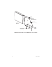
Mounting the Transmitter/Receiver Using the Wall Clip
NOTE:
Before mounting the FT8304 transmitter/FR8304 receiver to a wall, ensure that there is
adequate space at both ends for viewing the front-panel LEDs and for making the various rear-panel
cable connections.
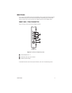
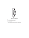
To attach the FT8304 transmitter/FR8304 receiver to a wall using the supplied wall clip, refer to
Figure 5 and do the following:
1. Using the two vertical or horizontal wall-mounting holes, attach the wall clip to a wall using
two screws (not provided).
2. Slide the module into the clip until the two holes on the bottom of the module align with the
two holes on the lower flange of the clip.
3. Attach the module to the clip using the two Phillips pan head screws provided for the clip.