2 Pelco Manual C1007M-B (2/96)
3.0 INSTALLATION
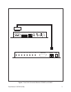
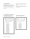
1. Connect the 9-pin interface cable (supplied with the
ICI3008/ICI3016 switcher) into the port labeled “RS
232” of the ICI3000P (refer to Fig.1).
2. Connect the modular phone plug of the interface
cable into the port labeled “DATA IN” on the
ICI3008/ICI3016 switcher (refer to Fig.1).
3. Connect the video inputs from your cameras to the
BNC’s labeled “VIDEO INPUTS” on the ICI3000P.
4. Connect a coaxial cable between the port labeled
“VIDEO OUT” of the ICI3008/ICI3016 and the port
labeled “VIDEO IN 1” of the ICI3000P.
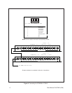
5. If multiple ICI3008/ICI3016 switchers are being
cascaded (i.e., linked to create a larger switcher), con-
nect a coaxial cable from the last video input of the
first Inter-Check
®
switcher to the port labeled
“VIDEO OUT” of the second Inter-Check
®
switcher.
Remove the cover of the second Inter-Check
®
switcher and set the 8-position dip switch to 0001
0000. Remove the cover of the first Inter-Check
®
switcher and set the 8-position dip switch to 0000
1000 (refer to Fig.2).
6. Connect the desired alarm outputs to any peripheral
equipment requiring a normally open contact using
the alarm interface connector supplied. Pin one cor-
responds to camera one; pin two with camera two;
etc. The separate wire from the Inter-Check
®
switcher
is ground. See Section 6.0 for alarm pin-out con-
figuration information.
7. Power up the Inter-Check
®
units using the transform-
ers supplied with each unit.
8. To verify communication between the Inter-Check
®
switcher and the ICI3000P, press [F9]. Press [F9]
again. Next, select camera one by entering a [1] one
followed by the [ENTER] key. The first red light
labeled [1] on the first switcher should be on. Re-
peat this step for each camera input on each switcher.
If an 8- or 16-position switcher has a second switcher
cascaded from it, selecting camera 8 or 16 respec-
tively will cause the first light of the second switcher
to be activated.
4.0 PROGRAMMING
NOTE: For a complete explanation of pro-
gramming features, refer to the programming
section of the operation manual supplied with
the ICI3000P.
4.1 REGISTER/CAMERA/ALARM
DWELL ASSIGNMENTS
To enter the programming mode, press [ENTER]. The
following menu will be displayed:
SELECT MENU
—————————————————————
1. Register # 1 or 2
2. Operator # 1 or 2
3. Exceptions on/off
4. Camera Select
5. Screen print on/off
6. Auto camera search on/off
7. Reverse video on/off
8. System Program
9. Exceptions Program
0. Syssave/sysread/hot key list
Press [8] (SYSTEM PROGRAM) and the following
menu will be displayed:
SYSTEM MENU
—————————————————————
1. # Chars./line
2. # Lines for small scrn 1 or 2
3. Small scrn position 1 or 2
4. Large scrn position 1 or 2
5. Alarm dwell time
6. Channel parms
7. Printer parms
8. Set clock
9. Ext. cam. select
0. Shadow list
Press [0] (SHADOW LIST) and the following prompt
will be displayed:
Shadow List
REG CAM DWL
1.
ESC to exit or CR to edit!