


C2405M (8/02) 3
CABLE IS ACCESSIBLE
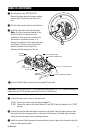
ᕡ Turn off power to the ICS100/ICS150.
Remove the lower dome and camera module.
Remove the PC board from the base of the
unit.
ᕢ Pull the video coaxial cable into the back box.
ᕣ Install the new board inside the back box.
Note: The block connector attached to the
new PC board is not required for this
installation. Either push the connector into
the conduit or completely remove it. To
remove the connector cut the wires attached
to the board. Cut the wires as close to the
board as possible so that they do not
interfere with the operation of the unit.
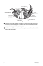
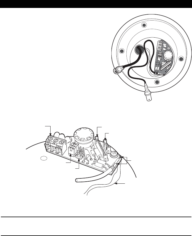
POWER
TERMINAL
24 VAC JUMPER
12 VDC JUMPER
VIDEO CONNECTOR
HEATER CONNECTOR
NOTE: CUT WIRES HERE
BLOCK CONNECTOR WIRES
ᕤ Connect the BNC video connector to the mating BNC connector.
CAUTION: The camera is set for 24 VAC operation at the factory. For 12 VDC operation remove the
jumper from the 24 VAC position and install it on the 12 VDC position.
ᕥ Connect the input power wires to the new board.
24 VAC: Connect the wires to the two blocks labeled 24.
12 VDC: Connect the wires to the blocks labeled 12 and GND. Move the jumper to the 12 VDC
position.
ᕦ Connect the camera video and heater connectors to the board. Plug the video connector from
the camera into the mating connector on the board. If the heater is installed, plug the heater
connector from the camera into the mating connector.
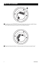
ᕧ Install the camera. Gently squeeze the camera bracket, place it against the shoulder inside the
base, and then gently release.