


Pelco Manual C558M (3/96) 3
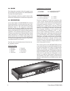
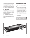
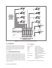
Figure 2. MPT9008CZ–Rear View
The MPT9008PZ/CZ is shipped with terminated BNC
inputs; however, the user can configure the unit for
loop-through operation. See Section 4.2 and Figure 3.
This makes it possible to loop signals through the
MPT9008PZ/CZ switcher/controller to an additional
switcher/controller and monitor at a remote location
where the signal is terminated. Any switcher can be
used at the second location and operate completely
independent of the first location.
4.0 INSTALLATION
MPT9008PZ/CZ Switcher/Controllers can be installed
in a number of configurations depending on your sys-
tem requirements. The two basic types of configuration
possibilities are shown in Figures 4 and 5, respectively,
depending on whether or not the unit is configured as
terminating or as loop-through.
4.1 TERMINATING CONFIGURATION
Both models of the switcher/controller are shipped from
the factory as homing, terminated units. See section 4.2
for configuring the MPT9008PZ/CZ for loop-through
operation.
4.2 NONTERMINATING LOOP-THROUGH
CONFIGURATION
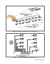
To configure the MPT9008PZ/CZ for loop-through
operation reference Figure 3 and perform the following
steps:
1. Remove power from the unit if not already done.
2. Remove the cover from the unit to expose the BNC
inputs located in the left, rear, back panel area.
3. Each BNC’s video input has a corresponding, like
numbered, front panel push button. Associated
with each BNC is a resistor as illustrated in Figure
3. Clip only the leads of those resistors whose video
input you wish to configure as being loop-through.
Figure 3, for example, shows the resistor lead for
video input #1 being clipped.
4. After making the desired changes, replace the cover
and resume operation.
NOTE: Looping switcher/controllers do not have
internal termination. Inputs must be terminated
with 75 ohms by other equipment in the system.