


6 Pelco Manual C1950M (10/98)
3.0 INSTALLATION
Refer to Table A for the type of video coaxial cable to use.
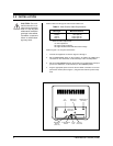
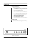
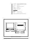
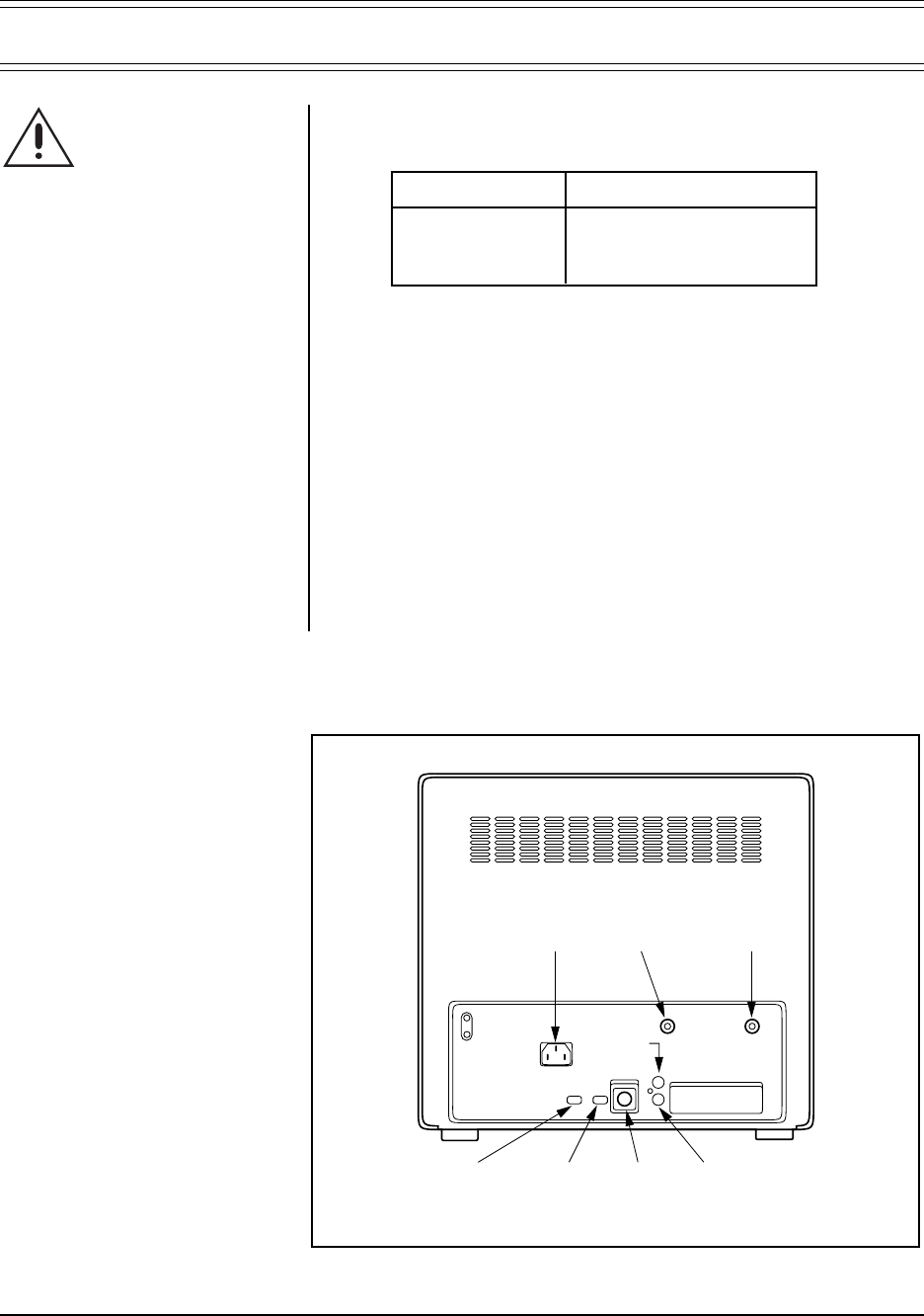
Refer to Figure 1 for rear panel connections.
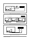
1. Connect the equipment as shown in Figures 2 through 4.
2. Set the IMPEDANCE switch on the monitor(s) to HIGH if the VIDEO OUT
connection is used. Otherwise, set the switch(es) in the 75-OHM position.
3. Set the S-VHS/CAMERA switch on the monitor(s) to S-VHS if the S-VHS input
jack is used. Otherwise, set the switch(es) in the CAMERA position.
4. Plug the appropriate power cord into the AC INLET connection on the rear
panel of the monitor (refer to Figure 1). Plug the other end into a power recep-
tacle.
CAUTION:
Do not in-
stall this monitor in a lo-
cation having excessive
heat or in any way that
obstructs the ventilation
openings in the cabinet.
Premature component
failure or cabinet dam-
age may result.
AC
INLET
IMPEDANCE
SWITCH
(HIGH/75Ω)
S-VHS/CAMERA
SWITCH
S-VHS
JACK
AUDIO OUT
JACK (RCA)
VIDEO OUT
JACK (BNC)
CAMERA INPUT
JACK (BNC)
AUDIO IN
JACK (RCA)
Figure 1. Rear Panel Connections
Table A. Video Coaxial Cable Requirements
Cable Type* Maximum Distance
RG59/U 750 ft (229 m)
RG6/U 1,000 ft (305 m)
RG11/U 1,500 ft (457 m)
* Minimum cable requirements:
75 ohms impedance
All-copper center conductor
All-copper braided shield with 95% braid coverage