4 Pelco Manual C933M (7/99)
CONNECTIONS
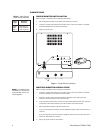
SINGLE-MONITOR INSTALLATION
Refer to Figure 1 and Table A for the following instructions.
1. Set the impedance switch on the back of the monitor to 75 ohms.
2. Connect a 75-ohm video cable from the video source, such as a camera, to the BNC
connector labeled IN on the back of the monitor.
3. Plug in the power cord.
Figure 1. Single-Monitor Installation
IMPEDANCE
75Ω HI
IN OUT
V-LINEAR V-SIZE FOCUS SUB-BRIGHT
IMPEDANCE
75Ω HI
IN OUT
FUSE
FUSE
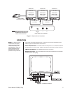
MULTIPLE-MONITOR INSTALLATION
Refer to Figure 2 and Table A for the following instructions.
1. Connect a 75-ohm video cable from the video source, such as a camera, to the BNC
connector labeled IN on the back of the first monitor.
2. Connect a 75-ohm video cable from the OUT connector on the back of the first
monitor to the IN connector on the second monitor.
3. If you are using a third monitor, connect a 75-ohm video cable from the OUT connector
on the back of the second monitor to the IN connector on the third monitor.
4. Set the impedance switch on the first monitor to HI.
If you are only using two monitors, set the impedance switch on the second monitor to
75 ohms.
If you are using three monitors, set the impedance switch on the second monitor to HI
and on the third monitor to 75 ohms.
5. Plug in the power cords for the monitors.
Cable Maximum
Type Distance
RG59 750 ft (229 m)
RG6 1,000 ft (305 m)
RG11 1,500 ft (457 m)
Table A. Video Coaxial
Cable Wiring Distances
NOTE:
In multiple-monitor
installations, a maximum of
three monitors can be con-
nected together.