C627M-A (8/03) 3
INSTALLATION
VIDEO INPUTS
Each of the two camera inputs is terminated in 75 ohms inside the splitter. So, if you loop a camera video line through a
monitor before routing to the splitter, be sure to set the monitor termination switch to HI-Z.
The camera whose video is routed to the camera 1 input will be the master camera. That is, pictures from the camera 2 input
will be inserted into the pictures from the camera 1 input.
The master camera can be an economical, random interlace type because the splitter can provide horizontal and vertical
synchronization for the second camera. However, a master camera having 2:1 interlace will provide greater synchronization
stability. Refer to the
Sync Output (H Drive – V Drive BNC Connectors)
section.
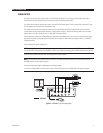
The second camera either must be independently synchronized to the master camera, or it must be a camera that can accept
horizontal and vertical synchronization from the splitter (refer to Figure 2). Refer to the
Sync Output (H Drive – V Drive BNC
Connectors)
section.
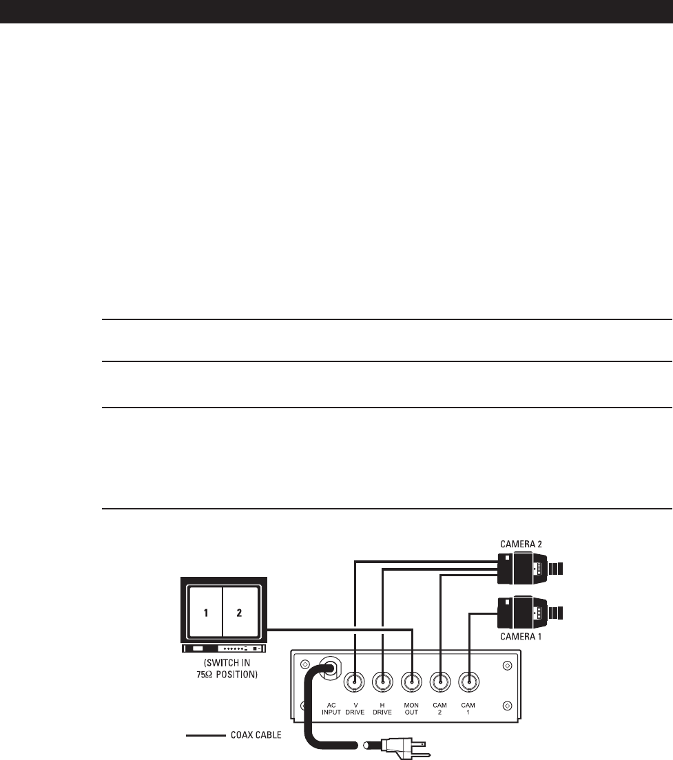
Figure 2 illustrates a typical configuration.
NOTE: (Applies to Figure 2 only.) Camera 2 must be equipped with three BNC connectors (one for VERT drive, one for HORIZ drive,
and one for VIDEO), and hooked to the VSS200DT. Camera 1 only needs to be equipped with one BNC connector for the VIDEO.
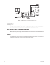
If you are using a camera with Gen. Lock, the configuration in Figure 3 applies.
NOTE: For installations using cameras with Gen. Lock only, the input termination resistor (R1) must be removed to let the
VSS200DT and the camera function properly.
During normal operation CAM 1 is designated as the master camera.
If you want to change CAM 2 to be the master camera, slide the S2 switch on the motherboard in the opposite direction.
Figure 2. VSS200DT Typical Configuration


