


SMART I/O User’s Manual
©1996 PEP Modular Computers GmbHMarch 12, 1996 Page 5 - 33
5
Chapter 5 Analog Modules
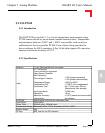
5.2.6 Configuration
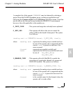
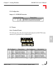
Jumper J1 - EEPROM Protection
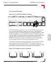
5.2.7 Pinouts
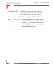
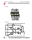
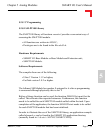
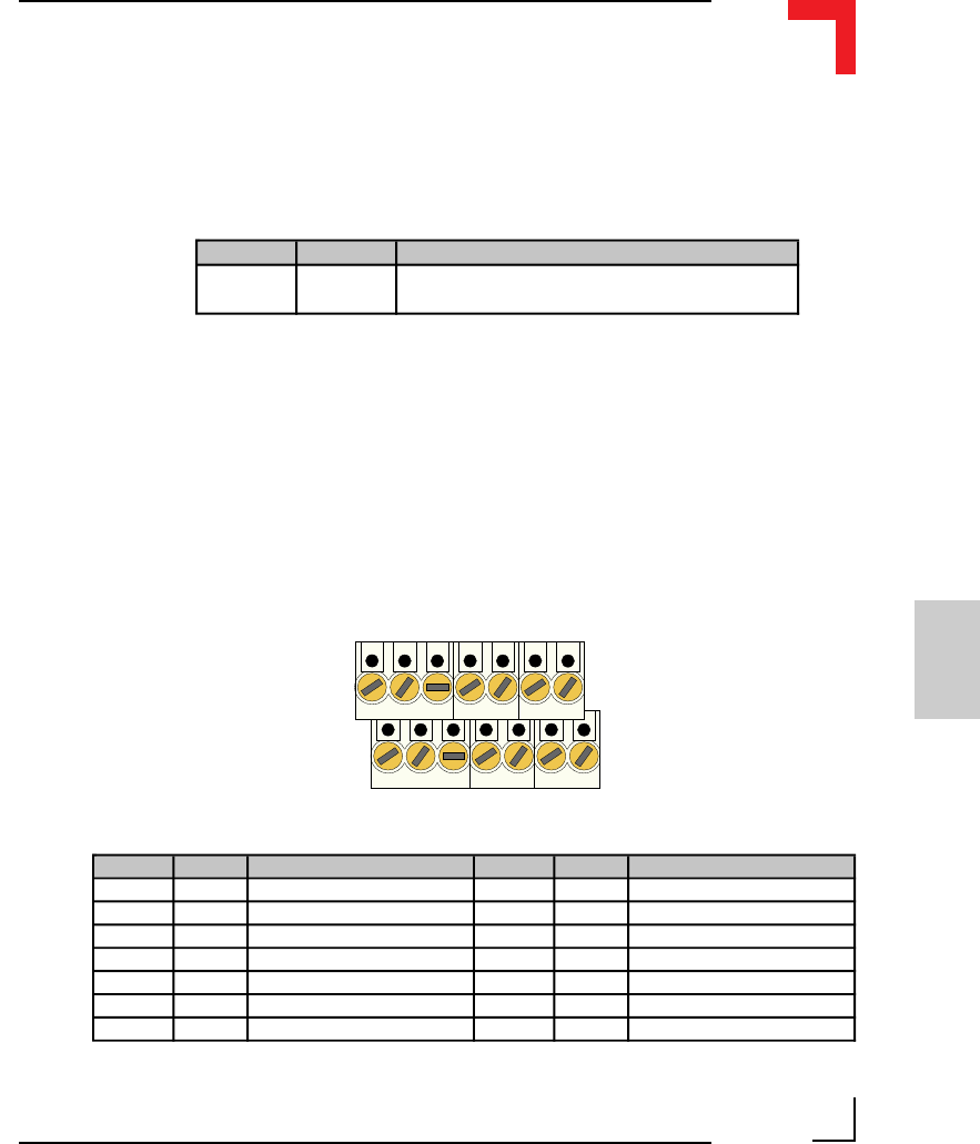
Screw Terminal Pinouts
The following shows the pinout/signal relationship for the SM-PT100 when
connected to a particular screw terminal block.
Pin 1
Pin 2
Pin 13
Pin 14
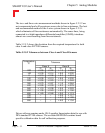
Pin Nr. Signal Description Pin Nr. Signal Description
1 Cur 0 400µA source for sensor 2 Cur 1 400µA source for sensor
3 In 0+ Sense line 0 positive 4 In 1+ Sense line 1 positive
5 In 0 - Sense line 0 negative 6 In 1 - Sense line 1 negative
7 AGND GND between 2 sensors 8 AGND GND between 2 sensors
9 In 2+ Sense line 2 positive 10 In 3+ Sense line 3 positive
11 In 2 - Sense line 2 negative 12 In 3 - Sense line 3 negative
13 Cur 2 400µA source for sensor 14 Cur 3 400µA source for sensor
Jumper Settings Description
J1
set EEPROM is not hardware write protected
open EEPROM is hardware write protected