


SMART I/O User’s Manual
October 01, 1996
©1996 PEP Modular Computers GmbH
Page 6- 20
Chapter 6 Communications Modules
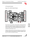
6.2.6 SSI Operation
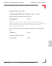
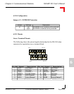
With reference to figures 6.2.6.1 and 6.2.6.2, the operation of the SSI inter-
face will be discussed.
• The position of the encoder disk is continuously clocked.
• Position data is ready for conversion by the parallel -> serial converter.
• The controller (SM-SSI) demands the axis angle from the encoder
which starts the SSI clock - the number of clock pulses required is
dependent on the data width (24-bits).
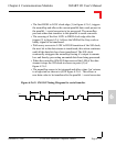
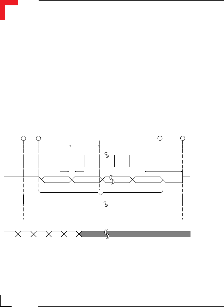
Figure 6.2.6.1: SM-SSI Timing Diagram
m = Stored parallel data T = SSI clock period
td = Delay time for the first clock G0 = LSB of Gray* code
Gn = MSB of Gray* code tm = Monoflop time
Tp = Pause time in SSI clock
* Binary code may also be converted.
1 2 3 4
T
td tm
Gn Gn - 1 G 1 G 0
m
m - 1 m m + 1
Clock
Serial Data
Monoflop P/S*
Parallel Data
Tp