


30
Section 3 — Link Interfaces Reference
Pinout Information
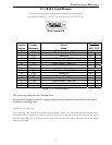
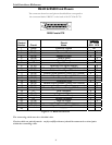
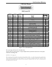
Each link interface available is described with detailed information on pin designation. Standard interface
cables will provide correct connections to modems, datasets, or DSU/CSUs.
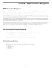
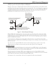
When connecting two bridge/routers back-to-back without modems, a null-modem cable is required to
crossover the pins on the links. Crossing over the pins allows two bridge/routers both configured as DTE
interfaces to be connected together. With this configuration, both bridge/routers will provide clocking for
the links, and each bridge/router must have a link speed defined.
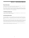
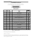
V.35 Module Identification:
V.35 links are provided as DB25 connectors on the back of the bridge/router, so an interface converter is
needed to convert to the standard V.35 connectors.
Link Clocking Information
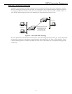
All of the link interfaces on the router act as DTE devices, this means that they may be directly connected to
DCE devices (modems, etc.) with the DCE devices providing the clocking for the link. The link speed is
controlled by the DCE device. Setting the link speed on the router will not result in a speed change on the
link.
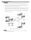
Some DCE devices allow the DTE devices connected to them to supply a clock signal which is then routed
back to the transmit clock pins on the DCE interface. This clock is then received by the link interface. By
using this method, the router may be in control of the link speed. The link speed may also be controlled by
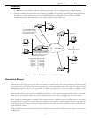
the router when a null-modem cable is used to connect two routers in a back-to-back configuration.
Changing the link speed within the menu system of the router changes the clock output speed that is
generated on the DTE Terminal Timing pins on the link interfaces.