


Link Interfaces Reference
31
The –P1705 and P1730 routers are currently produced with LXT CSU/DSU interface modules which have
their link speed configured in software (please see the PPP menus manual for configuration options);
however, the earlier model ATL CSU/DSU module is still compatible with the router and may be used with
it. Note that ATL master mode signaling is not compatible with the current standard 64K master mode
signaling; therefore, for back to back connections, an ATL unit will only operate at 64K when connected to
another ATL unit. If one interface is an ATL unit and the other is not, back to back operation must be set to
56K.
ATL CSU/DSU Link Module Information
The ATL CSU/DSU link module is normally configured to receive clock from the connected network.
When two ATL CSU/DSU link modules are to be used on a leased line in a back-to-back set-up, one of the
modules must provide the clock.
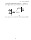
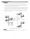
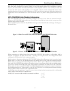
These modules may have either the UP/DOWN switch type or the ON/OFF slide switch type. Each type is
illustrated below.
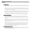
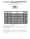
Figure 3 - 1 Rear View of ATL CSU/DSU Link Module with UP/DOWN Switches
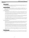
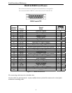
Figure 3 - 2 View of ATL CSU/DSU Link Module with Sliding ON/OFF Switches
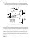
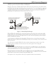
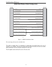
When connecting two bridge/routers back-to-back with CSU/DSU link modules, a null-modem cable is
required to crossover the pins on the links. Crossing over the pins allows two bridge/routers both
configured as DTE interfaces to be connected together.
Switch number 1 determines whether the ATL CSU/DSU link module will generate clocks or receive clocks.
When switch 1 is down (on), the normal position, the module receive clocks from the connected network.
When switch 1 is up (up), the module will generate clocks. When a pair of Routers are connected back-to-
back with ATL CSU/DSU link modules one module must be set to generate clocks and one module must be
set to receive clocks. On 64 Kbps units only, switch number 3 determines the mode of the ATL CSU/DSU.
When switch 3 is down (on), the CSU/DSU is in DDS (Digital Data Service) mode for normal connection to
the 64 Kbps digital service. When switch 3 is up (off), the CSU/DSU is in LDM (Limited Distance Modem)
mode for back-to-back connection with a null-modem cable.
On 56 Kbps units, the position of switch 3 is not a factor for back-to-back connection with a null-modem
cable. Switch 1 must still be set as noted above.
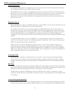
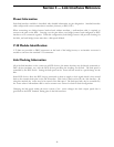
A DSU/CSU crossover cable would be constructed as follows: 1 --> 7
2 --> 8
7 --> 1
8 --> 2