


Perle S- 10G Media Converter Installation Guide
7
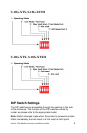
Test Function (Switch 2 – Test Mode)
Switch Position Type
Up (default) Built In Link Test
Down Loopback
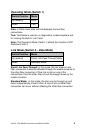
Built In Link Test: Switch 2 causes the S-10G to initiate the Built
In Link Tests on the specified port. Switch 3 determines the
specified port for the Built In Link Tests. If Switch 3 is Up, the tests
will be run on Port 1. If the Switch is Down the tests will be run on
Port 2. The other port will be disabled during these tests.
These tests consist of the media converter module generating test
patterns to be sent out the selected port to the remote media
converter. If the remote media converter is an S-10G, it will
automatically be put into loopback mode.
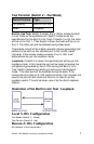
Loopback: If Switch 2 is down, the specified port will be put into
loopback mode. In this mode the port will be ready to receive the
test patterns generated by the S-10G running the Built in Link
Test. Switch 3 determines which port will be put into loopback
mode. The other port will be disabled during the tests. If the
remote device is also an S-10G media converter, this unit does not
need to be put into test mode and there is no need to set the
loopback switch. This will be taken care of by the Auto Loopback
feature.
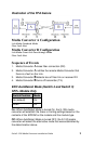
Illustration of the Built In Link Test / Loopback
Local S-10G Configuration
Test Mode (Switch 1 – Down)
Test Fuction (Switch 2 –Up)
Remote-S-10G Configuration
All switches in the Up position