


A470 Users Guide
Pertech® 2006
13
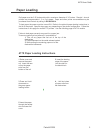
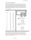
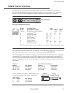
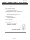
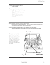
To change the conguration settings two banks of dip switches are located on the bot-
tom of the printer. On the Self Test & Conguration Report printout you can see the dip
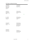
switch conguration for both banks. Below is a table that denes what each dip switch
controls. Cycle power for dip switch changes to take effect.
1 2 3 4 5 6 7 8
1 2 3 4 5 6 7 8
ON OFF = O = OPEN
= C = CLOSED
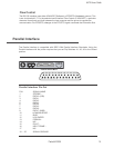
Conguring the Printer
Interface
Switch A-1 A-2 A-3
19.2k Baud O O O
9600 Baud O O C
4800 Baud O C O
2400 Baud O C C
1200 Baud C O O
600 Baud C O C
300 Baud C C O
Parallel C C C
Journal Line Feed
Switch A-4 A-5
5.3 Lpi O O
6.0 Lpi O C
6.9 Lpi C O
8.0 C C
Auto Line Feed
Switch A-6
On <CR>is<LF> O
Off <CR>is<CR> C
Serial Handshake
(RS-232 I/F Selected)
Switch A-7
RTS O
XON / XOFF C
Pin 13 Select
(Parallel I/F Selected)
Switch A-7
Form In O
Select Line C
RTS Polarity
(RS-232 I/F Selected)
Switch A-8
-12v (Mark) O
+12v (Space) C
Fault On Low Paper
(Parallel I/F Selected)
Switch A-8
Yes O
No C
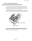
Pitch / Chars. Per Line
Switch B-1 B-2 B-3
12.0/33 O O O
13.1/36 O O C
14.4/40 O C O
16.0/44 O C C
18.0/50 C O O
20.6/57 C O C
24.0/66 C C O
Not Used C C C
Character Set
Switch B-4 B-5 B-6
Usa O O O
Uk O O C
German O C O
French O C C
Italian C O O
Spanish C O C
Hebrew C C O
Not Used C C C
Validtion Clamp
Switch B-7
Closed O
Open C
Serial Data Format
Switch B-8
8 Bits O
7 Bits C
Dip Switch “A”
Dip Switch “B”
A7
A8