


17” CDT Color Monitor 107B7
16
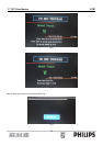
C. Then adjust focus VR1 to a fine vertical line.
D. Adjust focus VR2 to a fine horizontal line.
E. Repeat step C & D,after that ,set the Focus VR,G2 VR with the white lacquer.
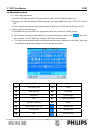
5. Purity Adjustment
A. Be sure that the display is not being exposed to any external magnetic fields.
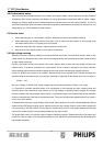
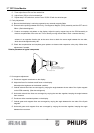
B. Ensure that the spacing between the Purity, Convergence, Magnet, (PCM), assembly and the CRT stem is
29mm. (See below diagram)
C. Produce a complete, red pattern on the display. Adjust the purity magnet rings on the PCM assembly to
obtain a complete field of the color red. This is done by moving the two tabs in such a manner that they
advance in an opposite direction but at the same time to obtain the same angle between the two tabs,
which should be approximately 180'.
D. Check the complete blue and complete green patterns to observe their respective color purity. Make minor
adjustments if needed.
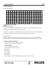
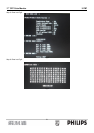
Relative placement of typical components
Purity Magnets
Deflection Yoke
4-pole Convergence Magnets
6-pole Convergence Magnets
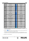
6. Convergence adjustment
A. Produce a magenta crosshatch on the display.
B. Adjust the focus for the best overall focus on the display.
Also adjust the brightness to the desired condition.
C. Vertical red and blue lines are converged by varying the angle between the two tabs of the 4 pole magnets
on the PCM assembly. (See above diagrams)
D. Horizontal red and blue lines are converged by varying the two tabs together, keeping the angle between
them constant.
E. Produce a white crosshatch pattern on the display.
F. Vertical green and magenta lines are converged by varying the angle between the two tabs of the 6-pole
magnets.
G. Horizontal green and magenta lines are converged by varying the two tabs together, keeping the angle
between them constant.