


Display User Manual
3D Solutions
01 April 2009
20 of 25 ©2009 Philips Electronics Nederland B.V.
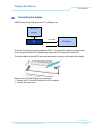
6 Interfaces
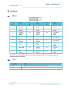
6.1 DVI-in
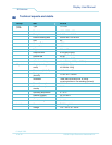
Pi
n
Signal Pi
n
Signal Pi
n
Signal
1 T.M.D.S.
Data2-
9 T.M.D.S.
Data1-
17 T.M.D.S.
Data0-
2 T.M.D.S.
Data2+
10 T.M.D.S.
Data1+
18 T.M.D.S.
Data0+
3 T.M.D.S.
Data2/4
Shield
11 T.M.D.S.
Data1/3
Shield
19 T.M.D.S.Da
ta0/5
Shield
4 No
connect
12 No
connect
20
No connect
5 No
connect
13 No
connect
21
No connect
6 DDC
Clock
14
+5V
Power
22 T.M.D.S.
Clock
Shield
7 DDC Data 15 Ground
(for +5V)
23
T.M.D.S.
Clock+
8 No
connect
16 Hot Plug
Detect
24 T.M.D.S.
Clock-
The DDC Clock and the DDC data are used by the Display Control Tool to control depth and
colour settings in the display.
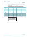
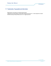
6.2 LED
LED Color Status
Red Display is in standby mode. No DVI clock is present.
Green Display on