


15
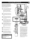
1
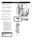
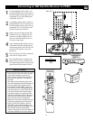
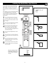
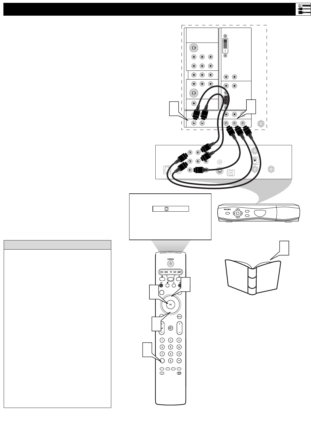
Using Component Video cables, con-
nect to the YPbPr jacks on the back of
the HD satellite receiver and to the cor-
responding AV3 or AV4 YPbPr jacks
on the back of the TV.
2
Using Stereo Audio cables, connect to
the AUDIO OUT jacks on the back of
the HD satellite receiver and to the cor-
responding AV3 or AV4 audio (L and
R) jacks on the back of the TV.
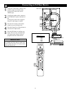
3
Refer to the user manual for the HD
satellite receiver to complete the con-
nections to the HD satellite receiver
and to use the HD satellite receiver’s
on-screen setup menus.
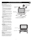
4
After completing HD satellite receiver
connections and setup through the on-
screen setup menus, press the AV+ but-
ton on the TV remote to access the
Source list.
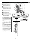
5
Press the Cursor Up or Down button to
select the AV4 input source.
6
Press the OK button to confirm your
choice. The set is now switched to the
AV4 input source for the viewing of pro-
grams from the HD satellite receiver.
Connecting an HD Satellite Receiver to YPbPr
®
®
®
®
SAP
CONTROL
TIMER
ACTIVE SLEEP
CLOCK
AV+
PIP
SCREEN
FORMAT
SURF
TV
SURR
HD
INFO
SELECT
DNM
CC
AUTO
AUTO
P
DVI
G
S-VIDEO
G
S-VIDEO
RLV
RL
RL
RL
V
Pr Pb Y
RL
RL
Pr Pb Y
Pr Pb Y
RL
V
STANDARD/
HD INPUTS
STANDARD/
HD INPUTS
TUNER
RGB+HV
AV5 AV6
AV1MONSUB OUT AV2AV3AV4
OUT
SERVICE 1
2
C
IN FROM ANT SATELLITE IN
OUT TO TV
CH 3
CH 4
DIGITAL
AUDIO OUT
VCR
CONTROL
S-VIDEO
VIDEOVIDEO
RR
PB
PR
Y
L
L
AUDIO
AUDIO
RF
REMOTEPHONE JACK
Source
OK
POWER
SELECT
GUIDE
INFO
HIGH DEFINITION
POWER
1
2
4
5
5
6
3
User Manual
for
HD Satellite
Receiver
___
AV3:Other
AV4:Other
AV5:Other
AV6:Other
SIDE
:Other
Back of TV
Back of HD
Satellite Receiver
(example only)
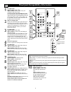
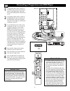
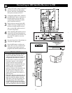
• To simplify making connections, the con-
nectors on audio and video cables are often
color coded to match the colors on TV
jacks: green for Y, blue for Pb, and red for
Pr; also red for right audio, and white for
left audio.
• The names for the component video jacks
may differ depending on the DVD player or
accessory digital source equipment used.
For example, besides YPbPr, you may see
R-Y/B-Y/Y; or CrCbY. Although abbrevia-
tions and terms may vary, the letters B and
R stand for the blue and red color compo-
nent signal connectors, respectively, and Y
indicates the luminance signal. If necessary,
refer to the user manual for your DVD or
digital accessory for more information.
• Inputs AV3–AV6 allow horizontal and verti-
cal picture panning using the Cursor Left,
Right, Up, and Down buttons. The Side
input allows vertical picture panning; left
and right panning with the Side input is pos-
sible when the input has been labeled
“Game.” See pages 18 and 19 for details on
side panel connections and source labeling.
HELPFUL H
INTS