


17
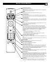
Connecting Surround Sound Equipment
®
®
®
®
PIP
SCREEN
FORMAT
SURF
TV
SURR
HD
INFO
SELECT
DNM
CC
DVI
G
S-VIDEO
G
S-VIDEO
RLV
RL
RL
RL
V
Pr Pb Y
RL
RL
Pr Pb Y
Pr Pb Y
RL
V
STANDARD/
HD INPUTS
STANDARD/
HD INPUTS
TUNER
RGB+HV
AV5 AV6
AV1MONSUB OUT AV2AV3AV4
OUT
SERVICE 1
2
C
+
-
+-
Audio
Input
Phase
180
0
4
4
1
3
DVI
G
S-VIDEO
G
S-VIDEO
RLV
RL
RL
RL
V
Pr Pb Y
RL
RL
Pr Pb Y
Pr Pb Y
RL
V
STANDARD/
HD INPUTS
STANDARD/
HD INPUTS
TUNER
RGB+HV
AV5 AV6
AV1MONSUB OUT AV2AV3AV4
OUT
SERVICE 1
2
C
General
Daylight saving
Change PIN
Subwoofer
Lamp rating
Lamp replaced
Settings
No • Yes
5
6
8
7
9
9
General
Daylight saving
Change PIN
Subwoofer
Lamp rating
Lamp replaced
Settings
Yes • No
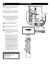
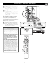
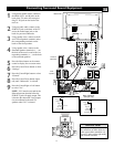
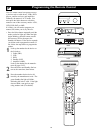
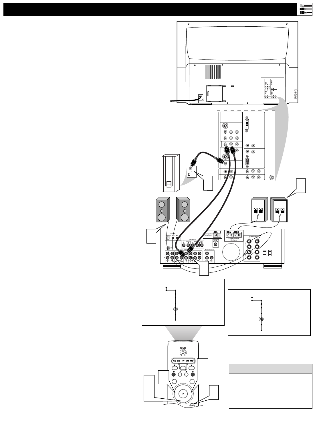
Back of TV
Back of Receiver
(example only)
Surround (Back)
Speakers
Front
Speakers
Powered
Subwoofer
1
Using Stereo Audio cables, connect to
the MON OUT L and R jacks on the
back of the TV and to the correspon-
ding TV IN jacks on the back of the
receiver.
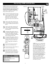
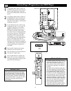
2
Using an Audio cable, connect to the
SUB OUT jack on the back of the TV
and to the Audio Input jack on the
back of a powered subwoofer.
3
Using speaker wires, connect to the R
and L Front Speakers terminals and to
the corresponding terminals on the
backs of the front speakers.
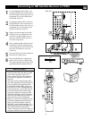
4
Using speaker wires, connect to the
Surround Speakers terminals (+, –) on
the back of the receiver and to the cor-
responding terminals (+, –) on the back
of the surround speakers.
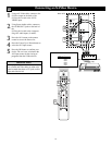
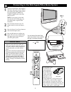
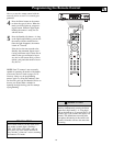
5
Press the Menu button on the remote
control to display the on-screen menu.
6
Press the Cursor Down button to select
“Settings.”
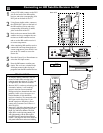
7
Press the Cursor Right button to select
“General.”
8
Press the Cursor Down button repeat-
edly until “Subwoofer” is selected.
9
Press the Cursor Right or Left button
to select “Yes.”
NOTE: “Yes” must be activated for the
Subwoofer menu selection before the
SUB OUT jack will supply output. This
is because the subwoofer’s low frequen-
cies are redirected to the main TV
speakers when “No” is selected.
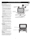
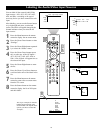
To simplify making connections,
the connectors on audio cables are
often color coded to match the col-
ors on TV jacks: red for right audio,
and white for left audio.
HELPFUL HINT