


ADAT-4 User Guide
Page 7
ADAT-4 Internal Jumpers
This section provides information about the ADAT-4’s internal jumpers and switches.
NOTE
For detailed instructions on opening and closing the ADAT-4, see “Inside the
Module.”
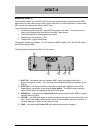
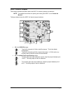
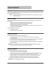
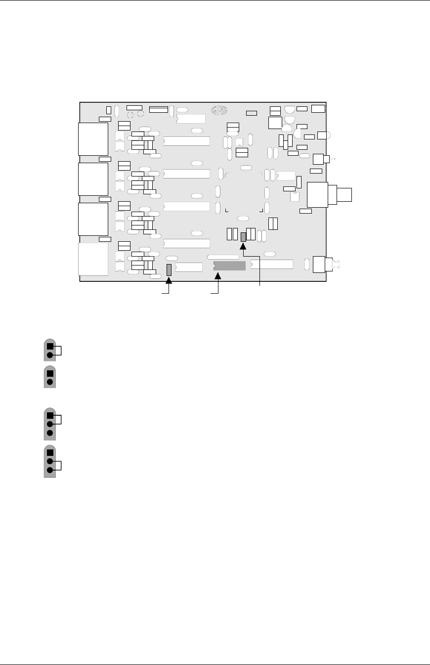
The figure below shows the ADAT-4’s internal jumper locations:
20/24 Bit
Jum
p
er
Word Clock
Polarit
y
Jum
p
er
ADAT-4
04-0236-
GRAHAM-PATTEN SYSTEMS
GRASS VALLEY, CALIFORNIA
Made in U.S.A.
J5
SW2
J2
Status
Di
p
Switch
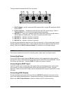
• J2 is the 20/24 Bit jumper.
1
2
– To set all 4 channels to 24 bits, install the jumper. This is the default
configuration.
1
2
– To set all 4 channels to 20 bits, remove the jumper. In 20-bit mode, any
auxiliary data on the AES inputs will be discarded.
• J5 is the Word Clock Input Polarity jumper.
1
2
3
– To leave work clock input reference normal, strap the jumper between pins
1 and 2. The rising edge is used as reference.
1
2
3
– To invert the work clock input reference, strap the jumper between pins 2
and 3. The falling edge is used as reference.