


13
1. Functions in each area
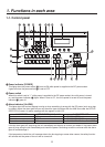
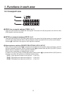
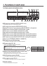
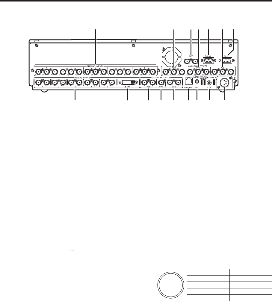
1-6. Rear panel connections area
SDI signal input connectors [DIGITAL INPUTS 1 to 5]
IN: SDI signal input; OUT: active through output
DVI-I signal input connector [DIGITAL INPUTS 6 DVI-I]
Analog HD component input connectors [ANALOG INPUTS 1 to 5] (optional)
PGM output connectors [DIGITAL OUTPUTS PGM 1, 2] (SDI)
PVW output connector [DIGITAL OUTPUTS PVW 1] (SDI)
AUX output connectors [DIGITAL OUTPUTS AUX 1, 2] (SDI)
PGM output connector [ANALOG OUTPUTS PGM 1] (analog HD component)
PVW output connector [ANALOG OUTPUTS PVW 1] (analog HD component)
AUX output connector [ANALOG OUTPUTS AUX 1] (analog HD component)
Ethernet port [ETHERNET] (10BASE-T, 100BASE-TX)
GPI input connector [GPI] (auto take)
For details on connection, refer to “6. External interfaces”.
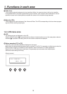
DC power socket [12V IN]
The DC 12 V voltage is supplied to this socket.
Use the AW-PS505A AC adaptor.
Note
When using other power sources, make sure the output
is DC 12 V
2 V, 5 A.
Reference input connector/BB output connector [REF]
Loop-through output in the external sync mode.
BB signals output from both connectors in the internal sync mode.
RS-422 interface connector [RS-422]
For details on connection, refer to “6. External interfaces”.
Tally output connector [TALLY]
For details on connection, refer to “6. External interfaces”.
Ground connector
Connect to the system’s earth ground.
Pin No. Signal name
1 GND
2 NC
3 NC
4 DC12V