


Product Information
RETURN TO TOP OF THE PAGE
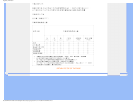
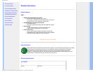
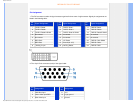
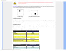
Pin Assignment
1. The DVI connector contains 24 signal contacts organized in three rows of eight contacts. Signal pin assignments are
listed in the following table:
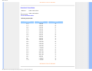
Pin
No.
Signal Assignment
Pin
No.
Signal Assignment
Pin
No.
Signal Assignment
1
T.M.D.S. Data2-
9
T.M.D.S. Data1- 17 T.M.D.S. Data0-
2
T.M.D.S. Data2+
10
T.M.D.S. Data1+ 18 T.M.D.S. Data0+
3
T.M.D.S. Data2/4 Shield
11
T.M.D.S. Data1/3 Shield 19 T.M.D.S. Data0/5 Shield
4
No connect
12
No connect 20 No connect
5
No connect
13
No connect 21 No connect
6
DDC Clock
14
+5V Power 22 T.M.D.S. Clock Shield
7
DDC Data
15
Ground (for +5V) 23 T.M.D.S. Clock+
8
* Analog V-sync 16 Hot Plug Detect 24 T.M.D.S. Clock-
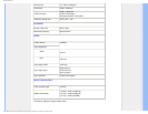
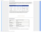
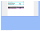
2. The 15-pin D-sub connector (male) of the signal cable:
Pin
No.
Assignment
Pin
No.
Assignment
1
Red video input
9
+5V
2
Green video input/SOG
10
Logic ground
3
Blue video input
11
Ground
file:///D|/EDFU/LCD/190C7/manual/english/190c7/product/product.htm (5 of 7)2006-12-06 ¤U¤È 05:45:04