


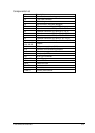
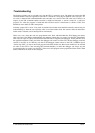


38-pin Mictor JTAG Debug & ETM Trace Connector (P2)
Signal Pin Pin Signal
Not used 1 2 Not used
Not used 3 4 Not used
GND 5 6 TRACECLK
Not used 7 8 Not used
CPU_RESET 9 10 Not used
CPU_TDO 11 12 T3V3
GND 13 14 Not used
CTCK 15 16 GND
CPU_TMS 17 18 GND
CPU_TDI 19 20 GND
CPU_TRST 21 22 GND
GND 23 24 P1.19
GND 25 26 P1.18
GND 27 28 P1.17
GND 29 30 P1.16
GND 31 32 P1.20
GND 33 34 P1.23
GND 35 36 P1.22
GND 37 38 P1.21
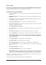
An external JTAG & ETM debug tool can be connected to a 38-pin Mictor P2 debug connector. Jumper J9 must
be set to 2-3 position when using an external debugger.
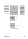
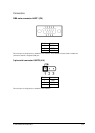
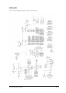
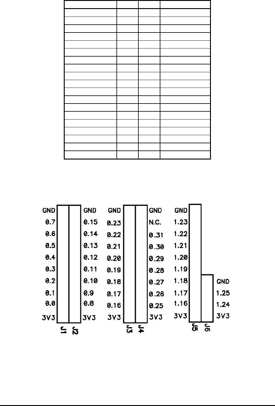
CPU expansion connectors
Figure 4: Expansion connectors
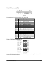
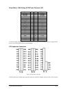
All CPU signals are available on the expansion connectors, which are standard connectors with a 2.54 mm raster.
iSYSTEM, December 2005 9/16