1 - Introduction ST7SB Socket Board User Guide
2/12
1 INTRODUCTION
The ST7SB socket board complements any ST7 programming tool that is
equipped for in-circuit programming (ICP) via a 10-pin ICC cable. For these
programming tools and emulators, the socket board provides the sockets required
to program ST7 FLASH microcontrollers without having to install them on an
application board.
Your socket board uses your programming tool ’s ICC connection and connects via
the ICC cable (See
Section 3.2.1
). The programming tool, then serves as the
hardware interface with your host PC running ST7 Visual Programmer (STVP7).
When using the ST7-STICK, users have the additional possibility of connecting
their socket board directly to the ST7-STICK using the female HE10-connector on
the bottom of the socket board (See
Section 3.2.2
).
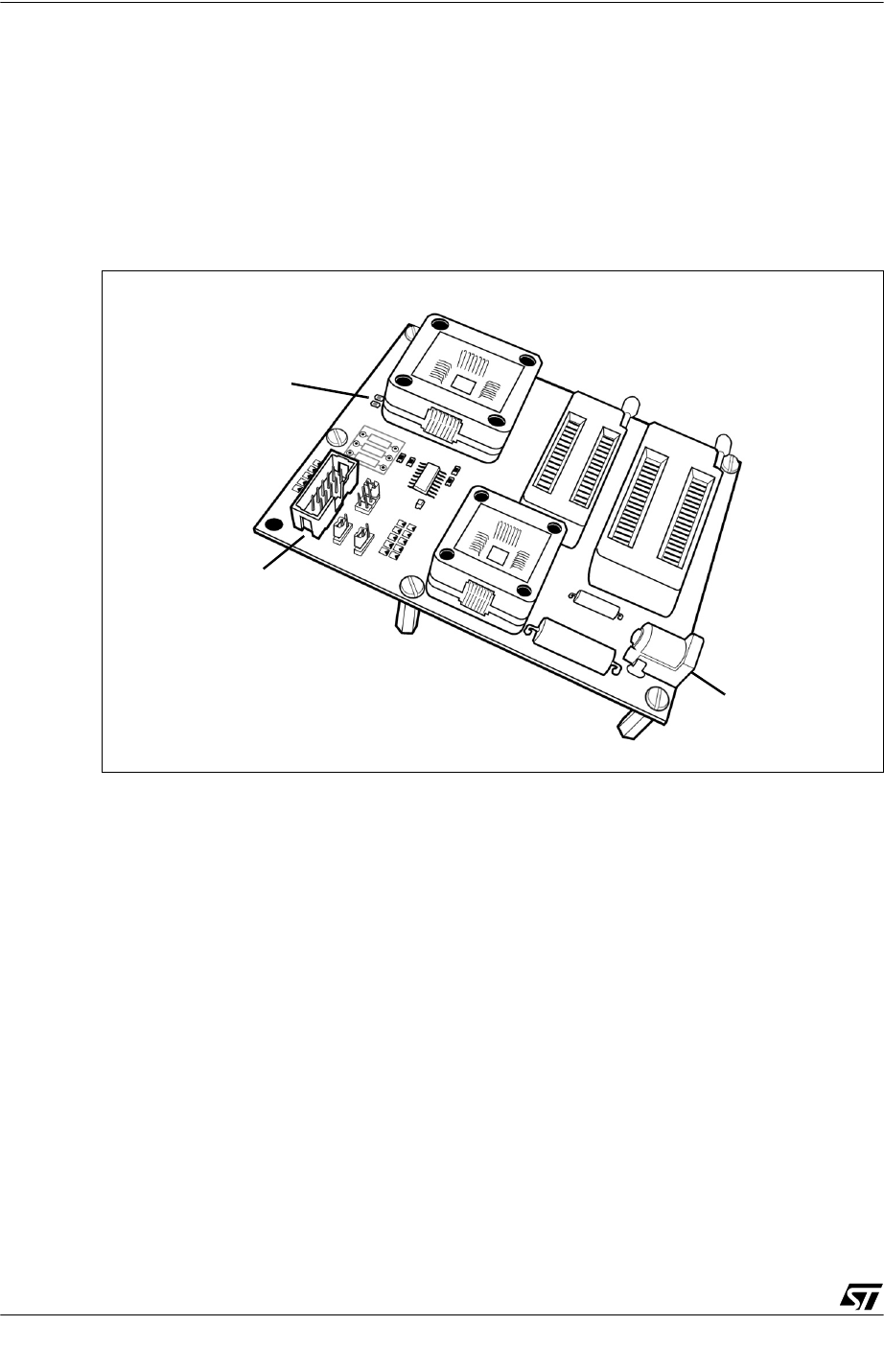
ST7SBxx socket boards are each designed to support the programming of a family
of ST7 microcontrollers (a typical example is shown in
Figure 1
). For this reason,
the layout of each type of socket board varies depending on the types of
programming sockets required to support a microcontroller family. However, the
general configuration and connection procedures explained here, remain the same
for all socket boards.
Figure 1: Typical ST7SBxx socket board
Status LEDs
ICC connector
(HE10 type)
Power supply
connector


