


35
Appendix B - Connector and Cable
Pin Outs
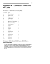
Pin Outs for V.35 Female Connector (DTE)
V.35 (DTE) Signal
A Chassis Ground <->
B Signal Ground <->
C Request to Send ->
D Clear to Send <-
E Data Set Ready <-
F Receive Line Signal Detect <-
H Data Terminal Ready ->
J Local Loopback ->
P Tx Data ->
R Rx Data <-
S Tx Data ->
T Rx Data <-
U Tx Clock Out ->
V Rx Clock In <-
W Tx Clock Out ->
X Rx Clock In <-
Y Tx Clock In <-
AA Tx Clock In <-
Pin Outs for DB-25 Male to DB-25 Female RS-232 Data &
AUX/Console Cable
The cable supplied with the BR Router is twenty-five conductors, straight through.
Connections on both the auxiliary interface and the data interface follow the
standard RS-232 pin outs. Note that the data interface may be set for synchronous
operation and in this mode the data interface will use the clock lines provided by
RS-232.