


- 43 -
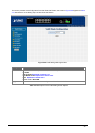
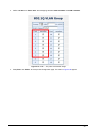
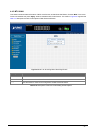
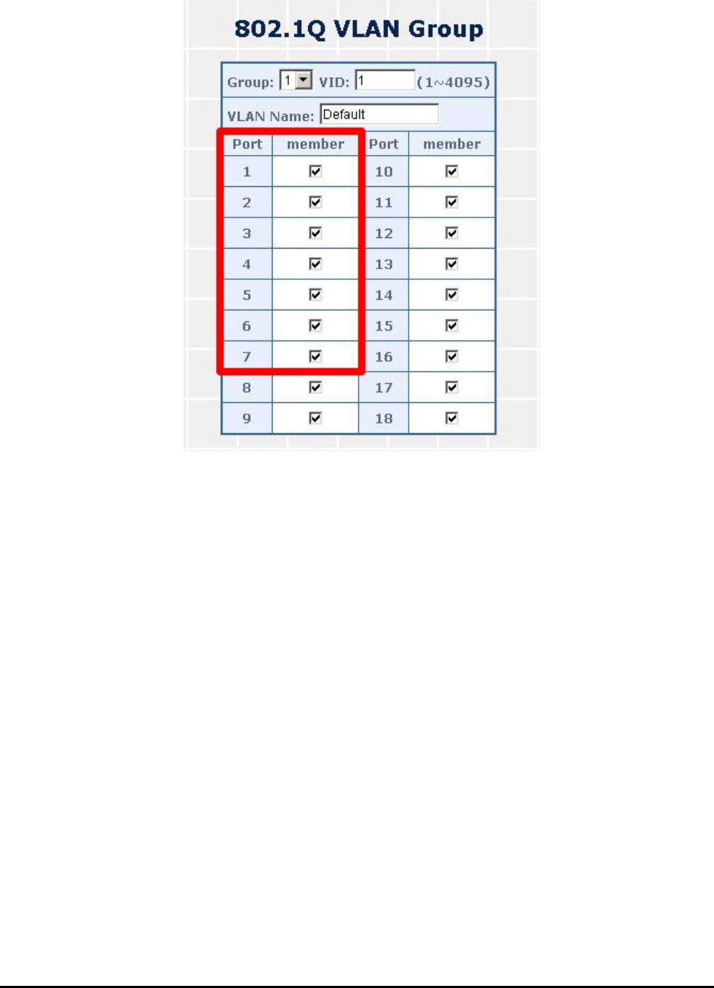
3. Define a VLAN 1 as a “Public Area” that overlapping with both VLAN 2 members and VLAN 3 members.
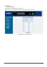
Figure 4-37 VLAN 1 – The public area member assign
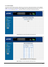
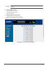
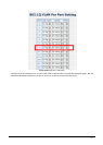
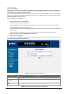
4. Setup Port-7 with “PVID=1” at VLAN per Port Configuration page. The screen in Figure 4-38 appears.