


PLANET Technology Corp. GRT-101/401 User’s Manual
- -
5
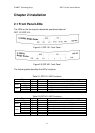
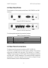
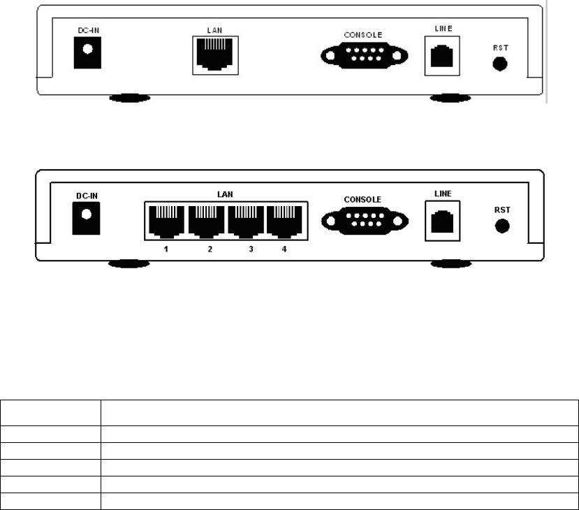
2.2 Rear Panel Ports
The connectors on the rear panel provide Power, LAN, CONSOLE and LINE
interfaces.
Figure 2-3 GRT-101 Rear Panel
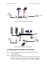
Figure 2-4 GRT-401 Rear Panel
The following table describes the connectors’ functions:
Table 2-2 Connector Functions
Connectors
Description
DC-IN Power adaptor inlet: Input voltage 9VDC
LAN Ethernet interface for LAN port (RJ-45)
CONSOLE RS- 232C (DB9) for system configuration and maintenance
LINE SHDSL interface for WAN port (RJ-11)
RST Reset button for factory default
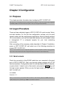
2.3 Rear Panel Connections
The figure shows the rear panel connections of GRT-101/GRT-401.
The STU-R is a standalone and can able to place in desktop. All the external
wiring shall be located at the rear panel. The LAN port is a 10 Base-T /
100Base-TX auto-sensing and half/full duplex Ethernet interface and complied
with IEEE 802.3 / 802.3u respectively. The console (RS-232C) interface for
configuration is menu-driven operation and can also be configured through
Ethernet interface by Telnet or Web-based operation.