


APPENDIX A NETWORKING CONNECTION
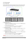
A.1 Switch‘s RJ-45 Pin Assignments
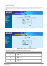
10/100Base-TX
Contact MDI MDI-X
1 1 (TX +) 3
2 2 (TX -) 6
3 3 (RX +) 1
6 6 (RX -) 2
4, 5, 7, 8 Not used Not used
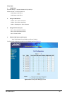
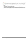
A.2 1000Mbps, 1000Base-T
Contact MDI MDI-X
1 BI_DA+ BI_DB+
2 BI_DA- BI_DB-
3 BI_DB+ BI_DA+
4 BI_DC+ BI_DD+
5 BI_DC- BI_DD-
6 BI_DB- BI_DA-
7 BI_DD+ BI_DC+
8 BI_DD- BI_DC-
Implicit implementation of the crossover function within a twisted-pair cable, or at a wiring panel, while not expressly
forbidden, is beyond the scope of this standard.
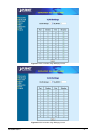
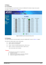
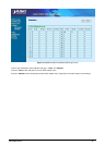
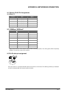
A.3 RJ-45 cable pin assignment
2 1 3 6
1
2
3
6
2 1
3 6
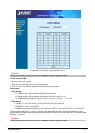
There are 8 wires on a standard UTP/STP cable and each wire is color-coded. The following shows the pin allocation
and color of straight cable and crossover cable connection:
EM-GSW2416SFv1 - 53 -