


- 7 -
Chapter 4 Connecting The Switch
This chapter describes how to connect the Switch to your Fast Ethernet
network.
PC to Switch
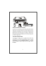
A PC can be connected to the Switch via a two-pair Category 3, 4, 5
UTP/STP straight cable. The PC (equipped with a RJ-45 10/100Mbps
phone jack) should be connected to any of the 5/8 numbered port.
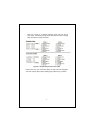
The LED indicators for PC connection depend on the LAN card capabilities.
If LED indicators are not light after making a proper connection, check the
PC LAN card, the cable, the Switch conditions and connections. The fol-
lowing are LED indicator possibilities for a PC to Switch connection: The
LNK/ACT and 100 LED indicators light green for hookup to 100Mbs speed.
The LNK/ACT lights green, while 100 LED off for hookup to 10Mbps speed.
Hub to Switch
A hub (10 or 100BASE-TX) can be connected to the Switch via a two-pair
Category 3, 4, 5 UTP/STP straight or crossover cable. The connection is
accomplished from the hub Uplink (MDI-X) or normal (MDI) port to any of
the Switch (MDI/MDI-X) ports:
A. 10BASE-T Hub
For a 10BASE-T hub, the Switch LED indicators should light up as the
following:
100 LED indicator is OFF.
LNK/ACT LED indicator lights green.
B. 100BASE-TX Hub
For a 100BASE-TX hub, the Switch LED indicators should light up as
the following:
LNK/ACT,100 LED indicators light green.