


7
Programmable Microelectronics Corp. Issue Date: February, 2004, Rev: 1.4
PMC Pm25LV512/010
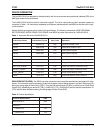
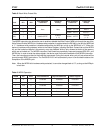
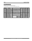
emaNnoitcurtsnItamroFnoitcurtsnIedoCxeHnoitarepO
NERW01100000h60hctaLelbanEetirWteS
IDRW00100000h40hctaLelbanEetirWteseR
RSDR10100000h50retsigersutatSdaeR
RSRW10000000h10retsigeRsutatSetirW
DAER11000000h30yrarrAyromeMmorfataDdaeR
DAER_TSAF11010000hB0deepSrehgiHtayromeMmorfataDdaeR
GORP_GP01000000h20yarrAyromeMotnIataDmargorP
ESARE_ROTCES11101011h7DyarrAyromeMnirotceSenOesarE
ESARE_KCOLB00011011h8DyarrAyromeMnikcolBenOesarE
ESARE_PIHC11100011h7CyarrAyromeMeritnEesarE
DIDR11010101hBADItcudorPdnarerutcafunaMdaeR
Table 1. Instruction Set for the Pm25LV512/010
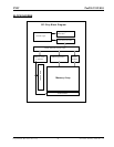
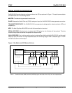
DEVICE OPERATION
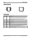
The Pm25LV512/010 is designed to interface directly with the synchronous serial peripheral interface (SPI) of the
6800 type series of microcontrollers.
The Pm25LV512/010 utilizes an 8-bit instruction register. The list of instructions and their operation codes are
contained in Table 1. All instructions, addresses, and data are transferred with the MSB first and start with a high-
to-low transition.
Write is defined as program and/or erase in this specification. The following commands, PAGE PROGRAM,
SECTOR ERASE, BLOCK ERASE, CHIP ERASE, and WRSR are write instructions for Pm25LV512/010.
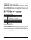
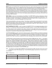
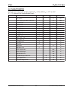
noitacifitnedItcudorPataD
DIrerutcafunaMhD9
:DIeciveD
215VL52mPhB7
010VL52mPhC7
Table 2. Product Identification
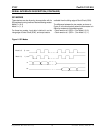
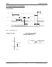
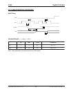
READ PRODUCT ID (RDID): The RDID instruction allows the user to read the manufacturer and product ID of the
device. The instruction code is followed by three dummy bytes, each bit being latched-in on Serial Data Input (SI)
during the rising edge of Serial Clock (SCK). Then the first manufacturer ID (9Dh) is shifted out on Serial Data
Output (SO), followed by the device ID (7Bh = Pm25LV512; 7Ch = Pm25LV010) and the second manufacturer ID
(7Fh), each bit been shifted out during the falling edge of Serial Clock (SCK).