


Part 6
IV. APPLICATION
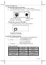
A. KEYBOARD CONSTRUCTION
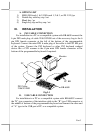
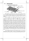
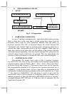
This keyboard is constructed of three parts on the top surface (ref. Fig.
4-1). A 6 position turning key switch area is at the upper right corner, a 15 x 6
matrix of push key switches occupies most of the top surface and a slot near
the right edge is designed for the Magnetic Stripe Reader of the -M2, -M3, -MJ
models.
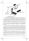
In the rectangular area at upper right corner there are one 6 position
electronic key switch and two LED’s. The upper LED is for power-on
indicator and under power-on LED is the MSR indicator (available in
KB-6600 only). The 6 position electronic key can be turned to one of the
following 6 positions: LP, L0, L1, L2, L3 and L4. It can only be taken out from
the switch at positions L0 and L1. The purpose of this electronic key serves 3
folds: When the key is switched to (and extracted from) position L0, the whole
keyboard output will be blocked off by hardware to work as a security measure.
A programmable answer back code for the final position of the 6 position
electronic key will be sent by the keyboard to the host computer whenever the
key is switched to a new position for a programmable delay time or when the
host computer sends a specific command to inquire the keyboard. The position
of the electronic key determines which page of the key content table for the 84
push keys applies, while the definitions of the same key within different pages
can be programmed so absolutely independent to provide instant menu change
over.
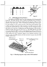
This turnable electronic key switch is delivered with a set of 4 pcs keys,
each marked as “PRG”, “REG”, “Z” and “GT”. The effective range of each of
the 4 keys can be illustrated by the following table and drawing (ref. Fig. 4-2).
MSR slot
MSR indicator (for KB-6600 only)
Power-on LED
6 position key
6 position key switch
15 x 6 push keys
Fig. 4-1