


Installation
3
Powerware
®
3110 User’s Guide S Rev B www.powerware.com
3. Start the UPS by pressing the switch as shown in Figure 2
or Figure 4 on page 4. The
µ indicator illuminates indicating
that power is available from the UPS output receptacles.
The unit beeps and the front panel LEDs illuminate several
times. The
µ indicator remains on, indicating normal
operation.
If the unit continues to beep, or if the
µ indicator is off even
though input power is available from the wall outlet, see
“Troubleshooting” on page 15.
NOTE Let the unit charge the battery for at least 3 hours. You may use the unit while
the battery charges, but the battery backup runtime will be reduced until the battery is
fully charged. This will take up to 8 hours after a full discharge while the UPS is fully
loaded.
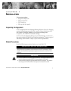
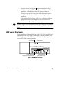
UPS Top and Side Panels
Figure 1 and Figure 2 identify features of the 120V (USA) models, with
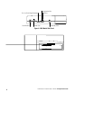
attached input line cord. Figure 3 and Figure 4 identify features of the
230V (European) models, which have a connector for the input line
cord as well as IEC output receptacles.
Fault Indicator
Output Receptacles
(Battery and Surge Protection)
Output Receptacles
(Surge Protection Only)
Power Indicator
Figure 1. 120V Model Top Panel