


is the circuit board that is screwed to the
Power Plant’s front panel.
Locate the chip
puller enclosed
with the
MultiWave II+
package. The
chip puller will
be used to care-
fully remove the
old microchip.
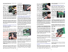
Notice the chip puller has
two small prongs. Put the
two prongs of the chip puller between the
chip and the socket on the left and right side.
There is a small gap between the chip and
the socket for you to insert the prongs of the
chip puller. It may take a little wiggling of the
chip puller to get its prongs under the chip.
Squeeze the chip puller together and pull
the microchip straight out of its socket. It
may take a tug. Pull straight back. When the
old microchip pops out of its socket, lay it
out of the way.
Removing the old MWII microchip from
the board you removed
First locate the MWII board you removed
from the Power Plant.
Using the same technique you used for
removing the front panel display chip, locate
the same looking chip on the separate MWII
board.
Note the small half moon and
white dot and
how it is orient-
ed in the socket.
You will need to
put the new chip
in exactly the
same way. Put
the two prongs
of the chip puller
between the chip and the socket on the left
and right side. There is a small gap between
the chip and the socket for you to insert the
prongs of the chip puller. It may take a little
wiggling of the chip puller to get its prongs
under the chip.
Squeeze the chip puller together and pull
the microchip straight out of its socket. It
may take a tug. Pull straight back. When the
old microchip pops out of its socket, lay it
out of the way.
Great work. You
are almost done.
Take a break.
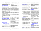
Take this time to
attach the anti-
static wrist strap
to your wrist by
wrapping the
clear sticky end
around your wrist like a bracelet. Remove
the adhesive strip from the copper tail and
attach it to an exposed aluminium surface
inside the Power Plant chassis.
Installing the new front panel display
microchip AND MWII card microchip
Carefully open the sealed end of the sil-
ver anti-static bag marked FRONT PANEL
DISPLAY (you are wearing your wrist strap
now, aren’t you?). Carefully remove the new
processor chip from the silver bag. The chip
is pressed to a small piece of black foam.
This special foam protects the chip from
static. Do not remove the chip from the
antistatic foam at this time.
Notice that the chip has a “half moon” on
one side. There is also a white dot to help
identify the direction. Looking from the rear
of the unit, this
dot must face to
the RIGHT on
the P600/P1200
and the LEFT
on the P300.
Note: Some
P600 models
may have the
display microchip aligned vertically with the
half moon and white dot facing UP.
Now, carefully use your fingers to pull the
chip straight out of the black protective
foam. Yep, you can use the chip puller for
this if you like. The key is pulling the chip
straight out of the foam so that we do not
bend any of the little legs.
After you pull the chip out of the foam, lay
it so it rests on its legs on top of the black
foam. It will look a lot like a bug - a healthy
bug with straight legs. If any of the legs are
not straight, use a finger nail to straighten
it.
Do not rush
the next step.
Please read
this next section
again before
you go on. Do
you have a light
shining inside
the Power Plant? Is it well lit? Do you have
your reading glasses on? Just checking.
You are going
to next insert
the chip into
the socket. Do
this by grasping
the small sides
of the chip with
your thumb and
forefinger. Now, carefully line up the legs
of the chip with the holes in the socket. BE
VERY CAREFUL. Only lightly press the chip
into the socket at this time - just enough for
the socket to hold the chip. You just want to
get the legs started. Do not press hard on
the chip at this time.
Now make sure each leg of the microchip
is inserted in the corresponding socket
hole. That’s what the little dentist’s mirror
is for. You should be able to see the pins
on the top of the socket with your eye. The
dentist mirror will help with the lower set of
pins. Most problems of MultiWave installa-
tion have been found to be people’s failure
to get the bottom row of legs in the socket
properly. Make double sure.
When you are sure that each leg of the
microchip is straight and lined up correctly,
top and bottom rows, press the microchip
down into the socket. The chip will seat
almost flush into the socket.
Now, use the mirror again to inspect the
microchip and socket. The microchip must
be flush in the socket and no pins should be
bent or coming out of the socket.
Install the new chip on the MWII oscilla-
tor card
Next, find the second silver anti-static bag
marked OSCILLATOR and replace the chip
on the MWII separate board with this new
one, following the same instructions for
safety and orientation as you just did on the
first chip installation.
Re-Installing the MWII oscillator board
Read this entire section before you
attempt to replace the oscillator board.
Now take the oscillator board in your hand.
Be careful to only touch the edges of the
board. Notice the printed warning on the
top of the board
indicating which
side of the board
must face the
front panel. The
new board must
only be inserted
in the correct
direction.
The electronic components on the oscillator
board must face forward, toward the face-
plate of the Power Plant. Never insert the
oscillator board so that the electronic com-
ponents face to the rear of the Power Plant.
Insert the oscillator board into its socket on
the Power Plant’s main board by pushing
straight down. Do not rock the card back
and forth.
Insert it
straight.
The board
must not be
inserted at
an angle.
If you are
working on
a P600 or
a P1200,
replace the
two small screws and nuts that hold the
oscillator board in place.
Inspect your work
You are almost done!
Carefully inspect you work one more time
before you button up. The items you want
to check will be:
• The new microchip on the front panel
display board is inserted correctly. Use that
mirror if you need to!
4 5