


2
Instructions for the DDI-11 DataPort Accessory Card
300mA
IN 1+
IN 1-
AGND
IN 2-
IN 2+
STBY
CGND
+15V
J1 J2
©
2004 QSC AUDIO
VM2
IM2
PROT
IM1
VM1
300mA
IN 1+
IN 1-
AGND
IN 2-
IN 2+
STBY
CGND
+15V
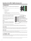
+15V (ref: CGND) supply
Chassis Ground
Power Suppy Standby
+
-
Analog (Signal) Ground
-
+
Channel 2 Balanced Input
Channel 1 Balanced Input
}
}
I. INTRODUCTION
The DDI-11 DataPort Accessory Card is designed for use with QSC amplifiers equipped with a
DataPort connector. It provide an easy way to exploit the features of the DataPort without using
QSControl or an accessory.
Through a terminal block with eight screw clamps on the DDI-11, the DataPort offers these
connections:
• Balanced input to Channel 1.
• Balanced input to Channel 2.
• Analog (signal) ground.
• Chassis ground.
• Standby control; connecting this terminal to chassis ground shuts off the power supply,
except on ISA Series amplifiers.
• +15 volts (at up to 300 mA), except on ISA and the original PowerLight Series* amplifiers.
The screw clamp terminals can accept stranded wire as large as 17 AWG (1 mm
2
) or solid wire as large as 16 AWG (1.5 mm
2
).
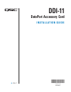
The DDI-11 card mounts onto the DataPort connector on the back of
the amplifier and secures to the amplifier with two screws. A
small sheet of insulative fish paper protects the underside of the
card.
To guard against oxidation, corrosion, or contamination, the circuit
board is treated with non-toxic protectants. Therefore, it may have
a slight odor and a slightly oily-feeling residue. Do not wash the
protectant off the circuit board.
INPUTS
Each channel of the amplifier has a balanced input connection on
the terminal block (see Figure 2). Each input comprises two
terminals, + (in polarity) and - (out of polarity). For optimum
immunity to noise, use a balanced connection whenever it is
possible.
For an unbalanced connection, connect the signal conductor of the
cable to the + input and the shield to the - input; also, connect a short jumper wire between the - input and the analog ground terminal.
With the amplifier channel at full gain, the input sensitivity (for 8-ohm loads) of the DataPort input is approximately 3 volts rms (+11.8 dBu).
ON/OFF CONTROL
A switch closure between the chassis ground and the standby terminals will put the amplifier’s power supply in standby. Opening the closure will
restart the power supply, with no inrush current surge. The standby terminal is isolated through a diode, so you can gang together any number of
amplifiers equipped with DDI-11 cards to be controlled by a single switch closure. ISA Series amplifiers, however, do not have this feature.
POWER SUPPLY
The +15 volt output is referenced to the chassis ground terminal and will provide up to 300 mA to power custom accessories or other devices. The
output is protected from short circuits or excessive current draw by a self-resetting polyswitch fuse.
The +15 volt terminal on ISA and original PowerLight Series* amplifiers, however, cannot provide enough current to power external circuitry. Doing so
may collapse an ISA amplifier’s internal low-level supply rails or burn out a series resistor on the input board of an original PowerLight amplifier.
II. ALTERNATE USES
The DDI-11 may also be used to connect to any DataPort connector on QSControl MultiSignal Processors and Basis products. Used this way, the
DDI-11’s four signal input terminals now become signal
outputs
, allowing you to use the audio signals for whatever purpose you require. The standby
and power supply terminals cannot be used in this application.
*
The original PowerLight Series comprises the models PL 1.0, PL 1.0
HV
, PL 1.4, PL 1.5
X
, PL 1.6
HVX
, PL 1.8, PL 2.0
HV
, PL 2.4
MB
, PL 3.4, PL 4.0, PL 6.0
PFC
,
PL 6.0 II, and PL 9.0
PFC
. It does not include the PowerLight 2 Series, which can be used to provide accessory power.
Figure 1. The DDI-11 and its control/monitoring
connections.
Figure 2. Eight screw clamp terminals offer connections for inputs, remote on/off
control, and a 15-volt DC supply.