


40
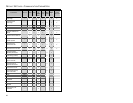
SCANNER AND CABLE TERMINATIONS
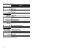
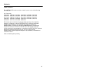
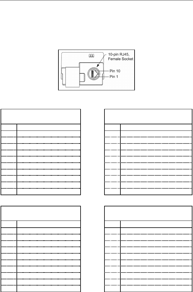
Scanner Pinout Connections
The MS3580 scanner interfaces terminate to a 10-pin modular socket.
The serial # label indicates the interface enabled when the scanner is shipped
from the factory.
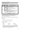
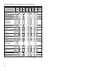
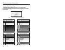
Figure 20. Bottom View of MS3580 (Stand Removed)
MS3580-47 Keyboard Wedge
and Stand-Alone Keyboard
MS3580-41
RS232C and Light Pen Emulation
Pin Function Pin Function
1 Ground 1 Ground
2 RS232 Transmit Output 2 RS232 Transmit Output
3 RS232 Receive Input 3 RS232 Receive Input
4 PC Data 4 RTS Output
5 PC Clock 5 CTS Input
6 KB Clock 6 DTR Input/LTPN Source
7 PC +5V 7 Reserved
8 KB Data 8 LTPN Data
9 +5VDC 9 +5VDC
10 Shield Ground
10 Shield Ground
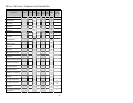
MS3580-40
Full Speed USB
MS3580-38
RS232 Low Speed USB
Pin Function Pin Function
1 Ground 1 Ground
2 RS232 Transmit Output 2 RS232 Transmit Output
3 RS232 Receive Input 3 RS232 Receive Input
4 RTS Output 4 RTS Output
5 CTS Input 5 CTS Input
6 USB D+ 6 D+
7 V USB 7 V USB
8 USB D- 8 D-
9 +5VDC 9 +5VDC
10 Shield Ground
10 Shield Ground