


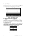
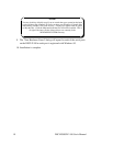
4.4 Options Register
The Options Register allows software to identify the DSCLP-100 as a
Quatech Enhanced Serial Adapter. It also allows software to set the UART clock
rate multiplier. Figure 9 shows the structure of the Options Register.
The powerup default of the Options Register is all bits zero.
Clock rate multiplier bit 0RR00
Clock rate multiplier bit 1RR11
(reserved, 0)-2
(reserved, 0)-3
(reserved, 0)-4
(reserved, 0)-5
ID bit 0ID06
ID bit 1ID17 (MSB)
DescriptionNameBit
Figure 9--- Options Register bit definitions
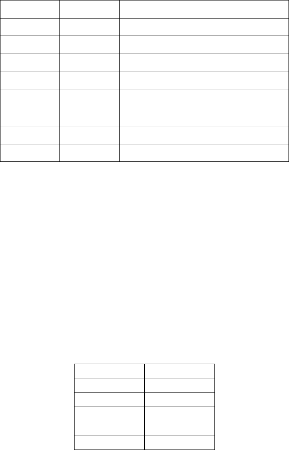
4.4.1 Enhanced Serial Adapter Identification
The ID bits are used to identify the DSCLP-100 as a Quatech Enhanced
Serial Adapter. Logic operations are performed such that the values read back
from these bits will not necessarily be the values that were written to them. Bit
ID1 will return the logical-AND of the values written to ID[1:0], while bit ID0
will return their exclusive-OR.
Software can thus identify a Quatech Enhanced Serial Adapter by writing
the ID bits with the patterns shown in the "write" column of Figure 10, then
reading the bits and comparing the result with the patterns in the "read" column.
Matching read patterns verify the presence of the Options Register.
0111
1001
1010
0000
ID0ID1ID0ID1
ReadWrite
Figure 10 --- ID bit write/read table
12 DSCLP/SSCLP-100 User's Manual