


Quatech Freedom USB Adapter User’s Manual Making external connections
All ports
RS-422/485 signal description
DB-9
Auxiliary Input (AuxIn–) 9
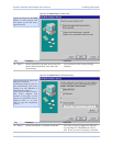
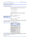
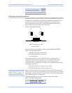
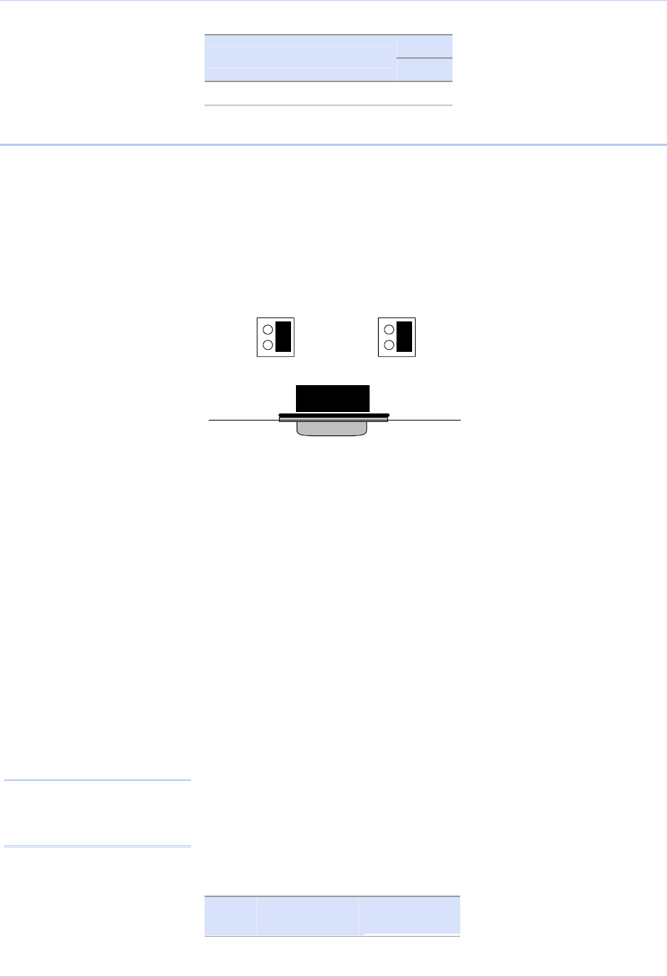
Configuring termination resistors
Factory installed resistors allow for Freedom USB-200/300 signal line
termination in compliance with RS-422 and RS-485 standards. You
can select or remove the desired termination by configuring the
associated jumper for each port. The following Figure shows the
factory default configuration: no termination.
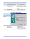
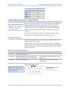
Figure 41 - RS-422/485 jumper settings
2
1
4
3
2
1
4
3
Factory Default = pins 3 & 4
(no termination)
J3 J2
CN1
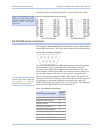
Jumpers J2 through J5 (DSU) or J2 through J9 (QSU/ESU/HSU)
allow the following selections:
RS-422 (100 ohm) termination
RS-485 (120 ohm) termination
no termination
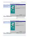
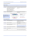
For normal operations over shorter distances or when using a
termination in the connecting cable, use the default setting. For
communications over great distances or if termination via the
connecting cable is not feasible, configure the jumpers for the desired
termination as follows.
RS-422 termination, jumper pins 1 and 3
RS-485 termination, jumper pins 2 and 4
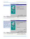
Only terminate signals that are present in the cable. If the auxiliary
input is not used and is not needed or wired in the cable, do not select
the auxiliary input termination on the board. See the following Table
for termination jumper assignments.
Note: To access the USB
adapter directly, remove the
four screws on the bottom of
the box and open the top cover.
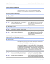
Configure each DB-9 connector as shown in the Table below.
Table 5 - RS-422/485 termination jumpers
Receive Data
(pins 4 and 8)
Auxiliary
Input
Rev 2.02 (2/24/2004) Page 31