


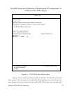
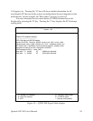
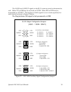
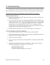

8.2 ESC-100M Channel Output Configuration
The ESC-100M connects to peripheral equipment through RJ-11 connectors, or
using the optional adapter cables, male D-25 connectors. When the RJ-11 connector is
converted to a D-25 connector, the adapter cables must be assembled with respect to
either a DTE or DCE configuration. The standard serial port connections are listed in
Figure 20.
6
5
6
20
4
6
AuxOut (DTR)
(RTS)
2535Receive Data (RxD)
7
4
7
4
Signal Ground
8
3
8
3
Carrier Detect
(DCD)
3222Transmit Data (TxD)
4
20
1
5
6
1
AuxIn (CTS)
(DSR)
D-25
RJ-11
D-25
RJ-11
DCE connectionDTE connection
RS-232 Signal
Description
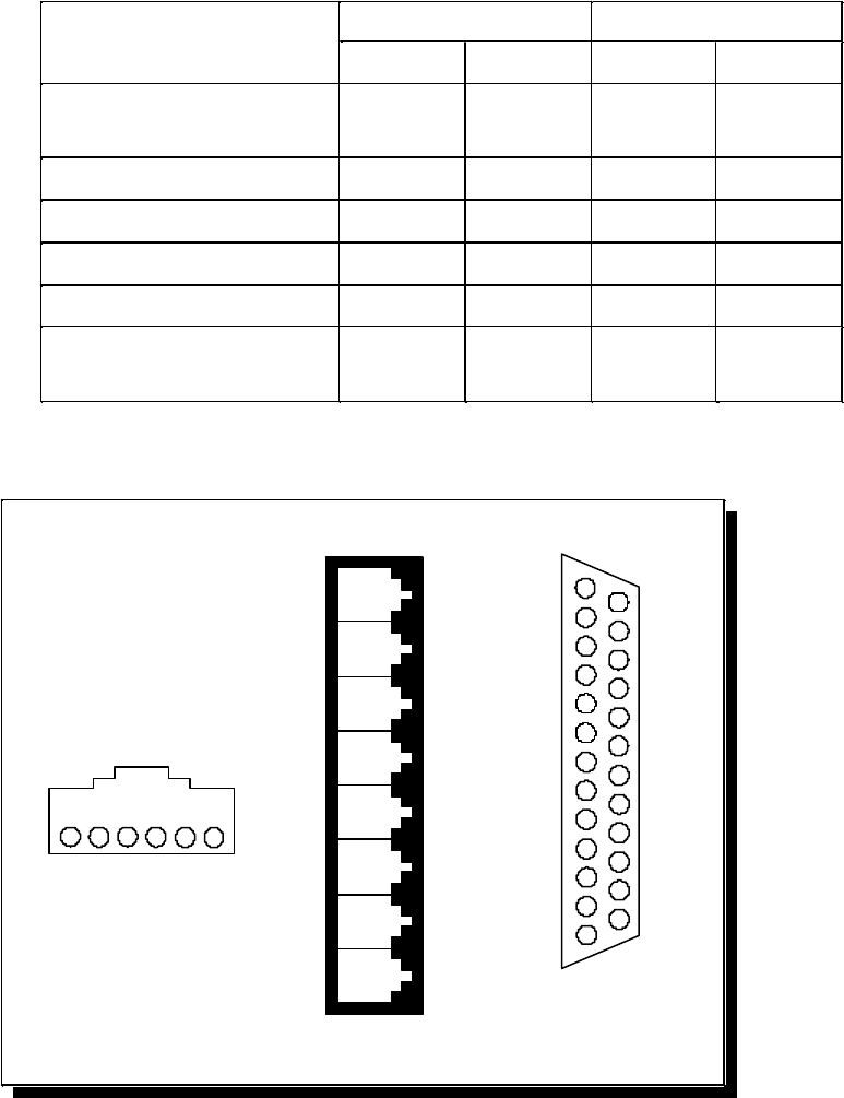
Figure 20 --- ESC-100M Connector Pinouts
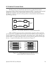
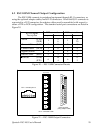
D-25 connector
(using adapter cable)
20
21
22
23
24
25
14
15
16
17
18
19
1
2
3
4
5
6
7
8
9
10
11
12
13
4
1
2 3 5
6
RJ-11 connector pinout
RJ-11 connectors in CN1
5
6
7
8
1
2
3
4
(Top of board)
Figure 21 --- ESC-100M Output Connectors
Quatech ESC-100 User's Manual
29