4.2.1 Command Line Options
To configure a QSP-200/300 in the system, the Enabler requires one command line argument
from the user to determine the configuration of the card. This argument must be enclosed in
parenthesis and within the argument, any or all of the following parameters may be specified
using a comma (no spaces) to separate each parameter:
Ssocket specifies which PCMCIA socket the QSP-200/300 must be inserted into for this
configuration argument to be used. socket must be in the range 0 - 15. This option is
always required.
Baddress specifies the base I/O address of the QSP-200/300 in hexadecimal and must reside
on an even 32-byte (20H) boundary. This option is required if the 'R' option is not
used.
Iirq specifies the interrupt level (IRQ) of the QSP-200/300 in decimal. irq must be one
of the following values: 3, 4, 5, 7, 9, 10, 11, 12, 14, 15, or 0 if no IRQ is desired.
This option is required if the 'R' option is not used.
Waddress specifies the base address of the memory window required to configure the
QSP-200/300. Set address = D0 for a memory window at segment D000, address =
D8 for a memory window at segment D800, etc. Valid settings for address are C8,
CC, D0, D4, D8, and DC. If this option is omitted, a memory window at segment
D000 will be used.
Omode specifies RS-422/485 output driver mode. The QSP-200/300’s ports may be
configured for either full duplex or half duplex operation with this option. If this
option is omitted, the default setting is the RS-422/485 ports are configured for full
duplex operation with the RS-422/485 output drivers always enabled. In half duplex
mode, the RS-422/485 transmitter may be enabled and disabled via the RTS (request
to send) or DTR (data terminal ready) signals. Both RTS and DTR are controlled
through the Modem Control Register of the 16550. See the Hardware Information
section for more information.
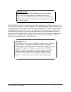
RTS Controlledo2
DTR Controlledo1
Always Enabledo0
Output Drivers Option
Figure 4. DOS Enabler Output Driver Options.
H instructs the Enabler to enable the RTS-CTS modem control handshake. When
modem control handshaking in enabled, the 16C550 UART’s RTS and CTS signals
are connected to the RS-422/485 auxiliary channel (AuxOut and AuxIn). The
auxiliary channel may then be used for handshaking between a QSP-200/300
RS-422/485 port and a peripheral device. When modem control handshaking is
disabled, the RTS and CTS signals from the 16C550 UART are looped back to each
QSP-200/300 User's Manual 24


