


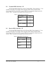

7. DIRECT MEMORY ACCESS
Direct Memory Access (DMA) is a way of transferring data on the ISA bus directly to
and from memory, resulting in high data transfer rates with very low CPU overhead. The ISA bus
DMA channel(s) to be used are selected through jumper packs J6 and J7. The sources for these
requests originate from the SCC and can be programmed for a variety of DMA modes. These
modes include DMA request on transmit, DMA request on receive, and DMA request on both
transmit and receive.
For DMA request on transmit, the DMA controller should be programmed first for an 8
bit read transfer on the desired channel, but not yet enabled. Then the SCC should be
programmed for DMA request on transmit on the desired DMA source. The sources for DMA
request on transmit are either the W/REQA pin (pin 10) of channel A or the DTR/REQA pin (pin
16) of channel A. The source is then determined by bit D0 of the Configuration Register. After
programming the SCC for DMA, DMA on the MPA-100 should be enabled by setting bit D2 of
the Configuration Register. Next, the DMA on the SCC should be enabled, and finally, the DMA
channel should be unmasked. The DMA controller will write the data in memory to the SCC.
When the transmit buffer of the SCC becomes empty, a DMA request will be generated and the
data will be transferred.
For DMA request on receive, the DMA controller should be programmed first for an 8 bit
write transfer on the desired channel, but not yet enabled. Next, the SCC should be programmed
for DMA request on receive on the desired DMA source. The two sources for DMA request on
receive are either the W/REQA pin (pin 10) of channel A or the W/REQB pin (pin 30) of channel
B. The source is then determined by bit D1 on the Configuration Register. After programming
the SCC for DMA, one should enable the DMA on the MPA-100 by setting bit D3 of the
Configuration Register. Then, the DMA on the SCC should be enabled, and finally the DMA
controller should be enabled. When a character enters the receive buffer of the SCC, a DMA
request is generated. The DMA controller then writes the data from the SCC into memory.
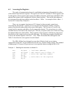
Programming for DMA request on both transmit and receive is simply a combination of
the two. There are three possible configurations that can be used, depending on the sources
selected. The first configuration available uses the W/REQA pin of channel A for DMA request
on receive, and the DTR/REQA pin of channel A for DMA request on transmit. This is done by
setting bit D0 and clearing bit D1 of the Configuration Register. The second configuration uses
the DTR/REQA pin for DMA request on transmit, and the W/REQB pin for DMA request on
receive. This is done by setting both D0 and D1 of the Configuration Register. The third
configuration uses the W/REQA pin of channel A for DMA request on transmit, and the
W/REQB pin of channel B for DMA request on receive. This is done by clearing bit D0 and
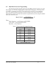
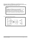
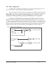
setting bit D1 of the Configuration Register. Figure 3 shows a block diagram of the DMA
circuitry on the MPA-100.
MPA-100 User's Manual 7-1