


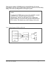


The testing signals the DTE can generate are the Local Loopback Test (LL) and the
Remote Loopback Test (RL). These signals are generated from the onboard Communications
Register. When a Test Mode (TM) condition is received, an interrupt can be generated on the
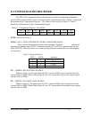
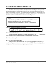
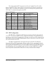
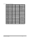
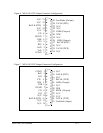
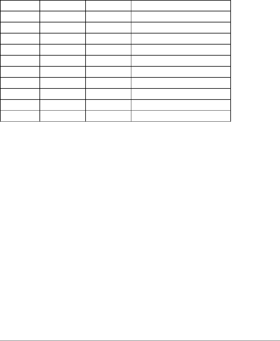
DTE. Table 16 summarizes the signals on the DTE.
Table 16 DTE Signals
INTM or Bit D7 of Comm RegXTM
Bit D4 of Comm RegXRL
Bit D5 of Comm RegXLL
RTXC pins of SCCXRxCLK
TRXCA pin of SCCXXTxCLK
DCDA pin of SCCXCD
DCDB pin of SCCXDSR
DTR/REQA of SCCXDTR
CTSA pin of SCCXCTS
RTSA pin of SCCXRTS
SCC Pin or Register BitGeneratedReceivedSignal
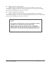
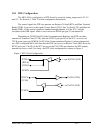
10.2 DCE Configuration
The MPA-100 is configured as a DCE device by correctly setting the jumper packs J2,
J11 and J12. See Section 5, Table 3 for this configuration information. It is noted that because
the connector used for the DCE configuration is the same one used for the DTE configuration the
MPA-100 does not have a true DCE implementation. However, the pin out is correct for a one to
one wired connection with a DTE.
The RS232C standard defines each signal with respect to the DTE. The difference
between the DTE and DCE signals is that, with the exception of a few control signals, the pins
used for signal transmission on the DTE are used for signal reception on the DCE and vice versa.
For example, pin 2 of the DCE connector is received data, yet the corresponding DTE signal is
the transmitted data. This correspondence allows the user to connect a DTE device to a DCE
device and perform communication without the use of any customized cable or adapter.
MPA-100 User's Manual 10-3