


Hardware Installation
100-8007-141G AirborneDirect™ Ethernet Bridge User's Guide Page 9
Quatech, Inc. Confidential
STANDARD PACKAGE HARDWARE DESCRIPTION
XX
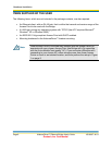
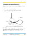
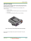
XXFigure 2XX identifies the components on the Bridge in its standard packaging. These components
include:
An external antenna.
An RJ-45 jack and cable attached to the Bridge.
A Reset switch on the bottom of the Bridge.
Three indicator Light Emitting Diodes (LEDs) on the top of the Bridge.
A mounting cradle.
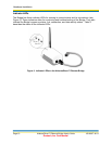
Figure 2. AirborneDirect™ Ethernet Bridge Hardware (standard package)
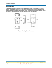
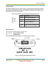
Reset Switch
The bottom of the AirborneDirect™ Bridge provides access to a Reset Switch. The Reset switch
returns all Bridge parameters to their factory default firmware settings. To reset Bridge
parameters, press (and hold) this switch for at least 5 seconds after power is applied to the
Bridge. To protect against accidental resets, the Reset switch is recessed.