


Chapter 2 Installation IPmux-16 Installation and Operation Manual
2-4 Installation and Setup
2.5 Installation and Setup
Setting Jumpers
IPmux-16 internal jumpers and switches do not need to be configured by the user
and therefore removing the product cover is not required.
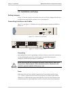
Connecting Interfaces and Cables
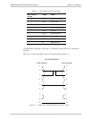
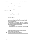
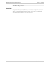
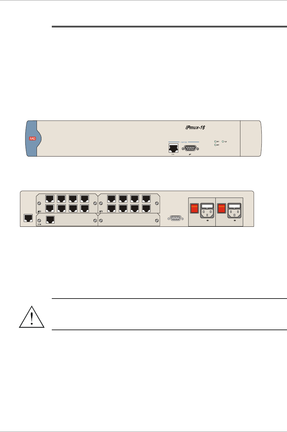
Figure 2-2 and Figure 2-3 illustrate the rear and front panel options available for
IPmux-16.
Figure 2-2. IPmux-16 Front Panel
PS2
PS1
~100-240VAC 3A T 125V~100-240VAC 3A T 125V
AL ARMS
POWERPOWER
O
O
I
I
EXT. CLK
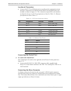
Figure 2-3. IPmux-16 Rear Panel
Grounding
Interrupting the protective grounding conductor (inside or outside the instrument)
or disconnecting the protective earth terminal can make this instrument
dangerous. Intentional interruption is prohibited.
Before switching ON this instrument and before connecting any other cable,
the protective earth terminals of this instrument must be connected to the
protective ground conductor of the power cord.
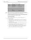
Fuses
Make sure that only fuses with the required rated current and specified type,
2 A T 250V as marked on the IPmux-16 rear panel, are used for replacement.
Whenever it is likely that the protection offered by fuses has been impaired, the
instrument must be made inoperative and be secured to prevent any operation.
Warning