


Front Panel Controls, Connectors, and Indicators 3-1
Chapter 3
Operation
3.1 Introduction
This chapter gives a detailed description of the front panel controls and indicators
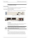
and their functions, explains power-on and power-off procedures, and provides
instructions for using a terminal connected to the IPmux-16 Control Port.
3.2 Front Panel Controls, Connectors, and Indicators
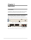
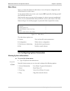
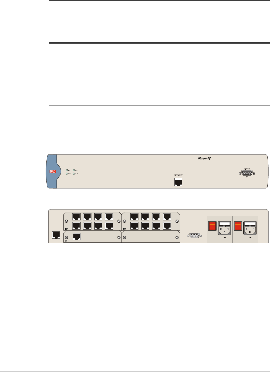
Interface modules installed in IPmux-16 have their own LED indicators (see
Figure 3-1 and Figure 3-2). The unit's LEDs are located on the right side of the front
panel.
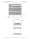
Figure 3-1. IPmux-16 Front Panel LEDs
PS2
PS1
~100-240VAC 3A T 125V~100-240VAC 3A T 125V
AL ARMS
POWERPOWER
O
O
I
I
EXT. CLK
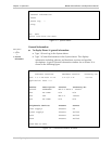
Figure 3-2. IPmux-16 Rear Panel Switch
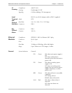
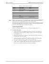
Table 3-1 lists the functions of the IPmux-16 system indicators and switches.