


Paragon II QSG 2
QSG-P2-0J-v4.5-E y 255-30-6010-00
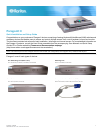
Package Contents
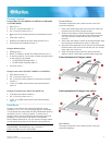
Forward Mount
Paragon Main Unit (P2-UMT242, P2-UMT442, P2-UMT832M,
or P2-UMT1664M):
The steps correspond to the numbers shown in the front
rackmount diagrams.
• Main Unit x 1
• 20-ft. (6.1-m) Cat5 test cable x 2
• 6-ft. (1.8-m) AC power cord x 1
• Rackmount kit (including brackets and associated screws)
x 1
• Cat5 admin cable x 1
• Raritan's User Manuals & Quick Setup Guides CD x 1
• Quick Setup and Installation Guide x 1
Paragon Stacking Unit:
• Stacking Unit x 1
• RUMT-1U-LM304 or RUMT-2U-LM304 rackmount kit x 1
• 6” stacking cable(s)—the number of cables vary depending
on the model you purchased
P2-UMT832S: Stacking cable x 1
P2-UMT1664S: Stacking cable x 2
• AC power cord x 1
Paragon user station (P2-UST, P2-EUST or P2-EUST/C):
• User-station module x 1
• 6-ft. (1.8-m) AC power cord x 1
• 6-ft. (1.8-m) AC power-extension cord for the connected
monitor x 1
• 16.4-ft. (5-m) DB9 male-to-female serial administration
cable x 1
Paragon IP-enabled user station (P2-USTIP1/2):
• IP-enabled user-station module x 1
• 6-ft. (1.8-m) AC power cord x 1
• 16.4-ft. (5-m) DB9 male-to-female serial administration
cable x 1
QS Rule
Rack Mount
Paragon II user stations and most KVM switches can be
mounted in 1U (1.75", 4.4 cm) of vertical space in a standard
19" equipment rack, except that P2-UMT1664M switch shall be
mounted in 2U (3.5", 8.9 cm) of space. To rack-mount a
Paragon switch, use the brackets and screws that came with
the device. To rack-mount a user station, use Raritan's
RUST-LM304 rackmount kit. You can mount a Paragon switch
or user station facing the front of the rack or facing the rear.
Note: If you lose or damage a switch's brackets, replace them
with the RUMT-1U-LM304 kit for any 1U switch or
RUMT-2U-LM304 for a P2-UMT1664M.
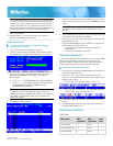
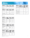
1. Secure the cable-support bar to the back end of the side
brackets using two of the included screws.
2. Slide the user station or KVM switch between the side
brackets, with its rear panel facing the cable-support bar,
until its front panel is flush with the “ears” of the side
brackets.
3. Secure the user station or switch to the side brackets using
the remaining included screws (three on each side).
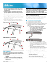
4. Mount the entire assembly in your rack and secure the side
brackets' ears to the rack's front rails with your own screws,
bolts, cage nuts, and so on.
5. When connecting cables to the rear panel of the user
station or switch, drape them over the cable-support bar.
Front rackmount of a Paragon switch
Front rackmount of a Paragon user station
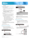
Rear Mount
The steps correspond to the numbers shown in the rear
rackmount diagrams.