


Chapter 1: Connections and Setup
Illustrations contained in this document are for representation only.
3
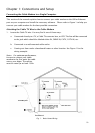
Cable Modem Overview
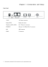
Front Panel
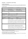
The following illustration shows the front panel of the EMTA machine:
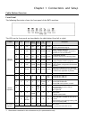
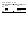
The LEDs on the front panel are described in the table below (from left to right):
THG540 Tel 2 Tel 1 Message
Cable
Activity
Cable
Link
PC
Link
Internet Description
X X OFF OFF OFF OFF FLASH
Tuning
(Searching downstream signal)
X X OFF OFF OFF FLASH FLASH
Ranging - Awaiting Response
(DS carrier acquire, ranging in process but
RNG-RSP has not been detected)
X X OFF OFF OFF FLASH FLASH
Any RNG-RSP detected
(Normalizing power level and timing offset)
X X OFF OFF FLASH FLASH FLASH
Connecting
(Ranging complete, DHCP in progress)
X X OFF FLASH FLASH FLASH FLASH
Configuring
(DHCP complete, configuration file download
in process)
X X FLASH FLASH FLASH FLASH FLASH
Registering and Baseline Privacy Initializing
(configuration file download complete, initialize
BPI if BPI is ON, registration in process)
Start-up
Operation
X X Enter Normal Operation Mode Registration complete
X X X X X X
OFF
ON
Internet ON-OFF switch off
Internet ON-OFF switch on
X X X X X
OFF
FLASH
ON
X
NO Ethernet/USB carrier present
Ethernet/USB TX/RX traffic
Ethernet/USB carrier present, no traffic
X X X X
OFF
FLASH
ON
X X
NO Cable Link
Cable BSS/OSS has set the CM into
de-activated state
CM is registered
X X X
OFF
FLASH
X X X
Internet ON-OFF switch off/No RF DS/US
network traffic
RF DS/US network traffic
Normal
Operation
X X
OFF
FLASH
X X X X
No message is delivered by the MSO
Email/Voice Mail is available for the user on
the server
(Implementation of the message waiting LED
will be via Proprietary MIB)
X X X X Wink X X
No service
Operation
Three seconds ON followed by a flash OFF
NACO =OFF
BPI unauthorized (when BPI is ON)