Direct Drive LCD Design Guide
2.3 Driver Mode Selection
There are several different modes of operation currently supported in the Direct Drive LCD driver. The
selection of operation mode depends on RAM type selection and LCD panel resolution.
2.3.1 SRAM_DD
Defining this macro selects a mode of operation that utilizes SRAM (or PSRAM) as the frame buffer. In this
operation mode, the ExDMA ACK signal supplies the Dot Clock during data transfer and the TPU supplies
the dot clock during blanking. This is currently the only mode supported on the H8S family of MCUs.
2.3.2 SRAM_NOMUX_DD
Defining this macro selects a mode of operation that utilizes SRAM (or PSRAM) as the frame buffer. In this
operation mode, the TPU supplies the dot clock during data transfer and blanking. This operation mode
can currently only be used on the H8SX on panels that do not require driving a “data enable” signal.
2.3.3 SDRAM_DD
Defining this macro selects a mode of operation that utilizes SDRAM as the frame buffer. In this operation
mode, the ExDMA ACK signal supplies the Dot Clock during data transfer and the TPU supplies the dot
clock during blanking.
2.3.4 SDRAM_CLUSTER_DD
Defining this macro selects a mode of operation that utilizes SDRAM as the frame buffer. In this operation
mode, the Bus Clock signal supplies the Dot Clock during data transfer and the TPU supplies the dot clock
during blanking. This mode is intended for LCD panels that have relatively high dot clock requirements
(VGA+) because the high speed Bus clock is used to drive the dot clock.
2.3.5 Dot Clock Hardware Connections
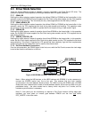
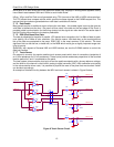
From the microcontroller, the EDACK signal is fed into a mux with the Dot Clock to ensure the clock edge
is sent at the time the valid data is on the bus.
Figure 4 H8S SRAM and H8SX SDRAM Dot Clock Logic
Note 1: When using the H8S devices, or the H8SX devices with SDRAM, it is also necessary to
connect the EDREQ (active low) line to the mux. This ensures that the clock remains
synchronized in the time between blocks of data. The H8SX running with SRAM uses a ExDMA
mode which has a deterministic number of clocks between blocks, and so can be relied on to give
predictable timing – the other modes have a latency which may take 4 or 5 clocks, and so
hardware synchronization is necessary.
Note 2: If the panel you are connecting to requires a Dot Clock inversion (falling edge data
transfers) you must place an inverter gate between EDACK and the mux
and define
DOT_INVERT in the driver code.
8


