


HD74LV2GT66A
Rev.2.00, Oct.17.2003, page 7 of 9
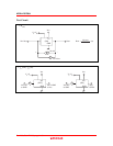
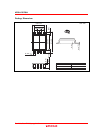
V
CC
V
CC
GND
(ON)
V =V
CIH
V
IN
V
OUT
C =
15 or 50 pF
L
• t ,t
PLH PHL
V
OL
V
OH
V
I
GND
t
f
t
r
90% 90%
Vref
Vref
50% 50%
t
PLH
t
PHL
10%10%
V
OUT
V
IN
V
CC
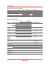
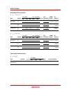
(V) Vref
t
r
/ t
f
3.3±0.3 2.5 V
V
I
INPUTS
50%
1.5 V3 V5.0±0.5
≤
3.0 ns
≤
3.0 ns
Notes: 1. Input waveform: PRR ≤ 1 MHz, Zo = 50 Ω.
2. The output are measured one at a time with one transition per measurement.
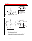
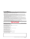
V
CC
V
CC
V
CC
GND
GND
Item S1 S2
V
C
V
IN
t
ZH
R =
1 k
L
Ω
C =15 or
50 pF
L
V
CC
GND
t
ZL
V
CC
GND
t
HZ
V
CC
GND
t
LZ
S1
R =
1 k
L
Ω
S2
V
OUT
• t ,t / t ,t
ZH ZL HZ LZ
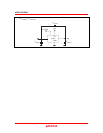
V
OH
V
I
GND
GND
t
f
t
r
90% 90%
Vref
Vref
50%
t
ZH
10%10%
V
OUT
V –0.3 V
OH
V +0.3 V
OL
V
C
t
HZ
50%
V
OL
V
CC
t
ZL
t
LZ
V
CC
(V) Vref
t
r
/
t
f
3.3±0.3 2.5 V
V
I
INPUTS
50%
1.5 V3 V5.0±0.5
≤
3.0 ns
≤
3.0 ns
waveform–A
waveform–B
Notes: 1. Input waveform: PRR ≤ 1 MHz, Zo = 50 Ω.
2. Waveform–A is for an output with internal conditions such that the output is low
except when disabled by the output control.
3. Waveform–B is for an output with internal conditions such that the output is high
except when disabled by the output control.
4. The output are measured one at a time with one transition per measurement.