( 19 / 54 )
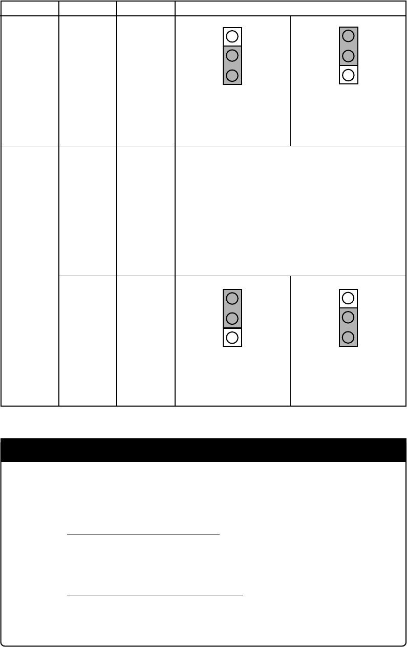
Switch No. Switch setting
Function
CNVSS
JP1
When connecting CNVSS
to the target system
(Factory-setting)
Applies the VCC voltage to
CNVSS. When not
connecting the target,
applies 5 V.
XCIN
JP1
When connecting X
COUT to
the target system
(Factory-setting)
When not connecting
X
COUT to the target system
Table 3.1 Switch settings of the M30220TF-PRB and FLX64-PRB
VDD
CNVSS
VDD
CNVSS
Board
M30220TF-PRB
XCOUTJP2
FLX64-PRB
The M30220TF-PRB does not use this switch.
XCIN is always selected in any setting.
PORT
NC
PORT
NC
IMPORTANT
Note on CNVSS:
• To debug the control program for CPU rewrite mode, you need to apply 4.5 to 5.5
V voltage to the CNVSS pin.
When the target system is connected:
Set the jumper switch JP1 of the M30220TF-PRB to "CNVSS". The CNVSS is
connected to the target system. Apply 4.5V to 5.5V voltage to the CNVSS pin of the
target system.
When the target system is NOT connected:
Set the jumper switch JP1 of the M30220TF-PRB to "VDD". 5V voltage is applied
from the emulation pod to the CNVSS.


