


( 5 / 7 )
6. Selecting a Clock
With the M32182T2-PTC, it is possible to select a clock
supply to the MCU by the clock select switch (SW1). Select
a clock supply as shown below.
However, when used with the M32182T2-PTC, the clock
cannot be supplied from the target system.
10 MHz: Supplies the clock (X1: 10 MHz) on the M32182T2-
PTC board to the MCU.
SOCKET: Supplies the clock to the MCU from the socket
(X2) for mounting the oscillator on the
M32182T2-PTC board. By mounting the oscilla-
tor to the X2 socket of the MCU, it is possible to
change the operating frequency.
For more details on the connecting the X2 socket
and the MCU, see Figure 5 (right).
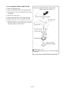
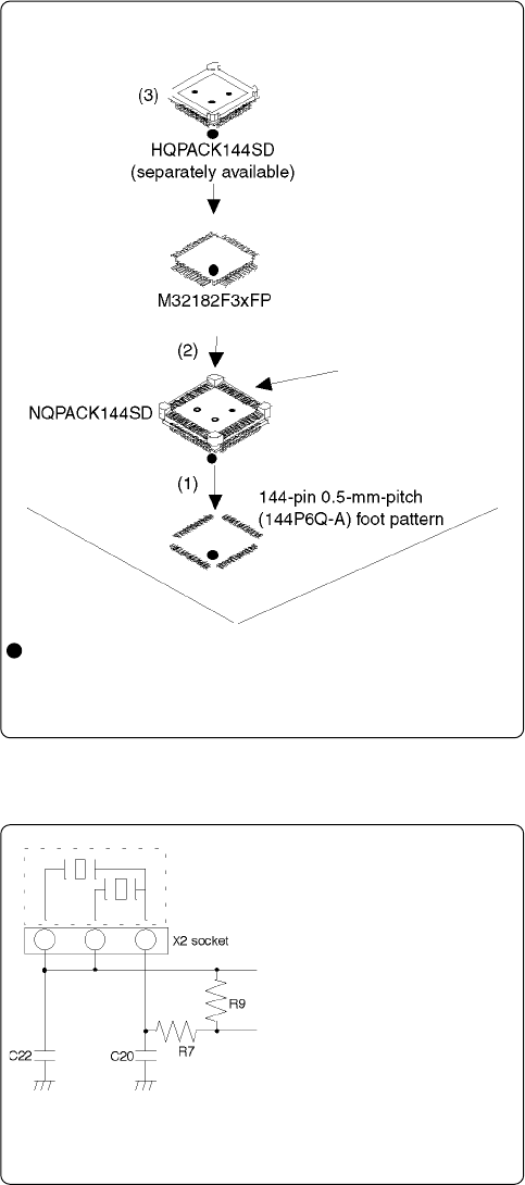
Figure 5 Connection diagram of X2 socket
Mount an oscillator to X2 as
shown in the diagram printed on
the board.
Connected to XIN pin of MCU
Connected to XOUT pin of MCU
R9: 1M Ω
R7: 510 Ω
C20: 27 pF
C22: 27 pF
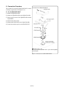
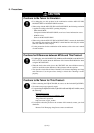
5.3 For Board-mounted Evaluation
(1) Mount the NQPACK144SD.
(2) Mount the M32182F3xFP on the NQPACK144SD.
(3) Mount the HQPACK144SD on the NQPACK144SD.
Figure 4 Connection for board-mounted evaluation
: Position of No. 1 pin
Be sure to match the position of No. 1 pin of the foot pattern
and each part.
Connection for board-mounted evaluation