


(3/4)
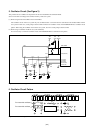
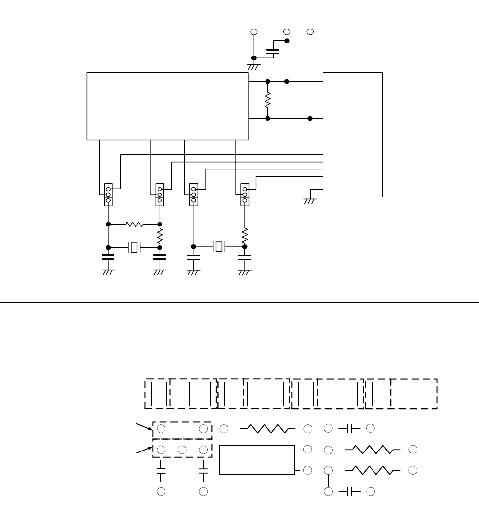
5. Oscillator Circuit (See Figure 3)
This product has two oscillator circuit patterns for the main clock XIN and sub-clock XCIN.
Select one of them according to the oscillator circuitry of the user system.
(1) When using the internal oscillator circuit of the MCU:
The oscillator circuit on the user system may not oscillate because a converter board is used between the emulator MCU and the
user system. In this case, set the jumper switch to INT and mount an oscillator circuit on the M38D59T-RLFS’s oscillator circuit
pattern. When using the oscillator circuit on the user system, be sure to set the jumper switch to EXT.
(2) When using an oscillator module IC etc. (self-oscillation):
It is not necessary to mount an oscillator circuit on the M38D59T-RLFS’s oscillator circuit pattern.
C3
C4
X1X2
R4
C1
C2
R3
XCIN XCOUT XIN XOUT
IC1
CN2-3a(P60)
CN2-2b(P61)
CN2-4a(XIN)
CN2-4b(XOUT)
CN1,CN2
VCC
CN2-5a(VCC)
TP1
RESET
CN2-2a(RESET*)
CN2-3b(VSS)
TP3
VCC
TP2
GND
+
JP3 JP4 JP1 JP2
R2
C5
RESET*
R1
EXT
INT
EXT
INT
EXT
INT
EXT
INT
Figure 3 Oscillator circuit diagram
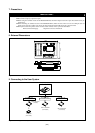
6. Oscillator Circuit Pattern
X1
C1 C2
R2
JP2 XOUTJP1 XIN JP3 XCIN JP4 XCOUT
X2
C4
R3
R4
C3
INT EXT INT EXT INT EXT INT EXT
For 3-terminal oscillator
For 2-terminal oscillator
Figure 4 Oscillator circuit pattern