Functional Specifications
2.4 Serial Port Interface
Rev.1.00
Oct 09, 2008 2-6
REJ11J0021-0100
2
2.4 Serial Port Interface
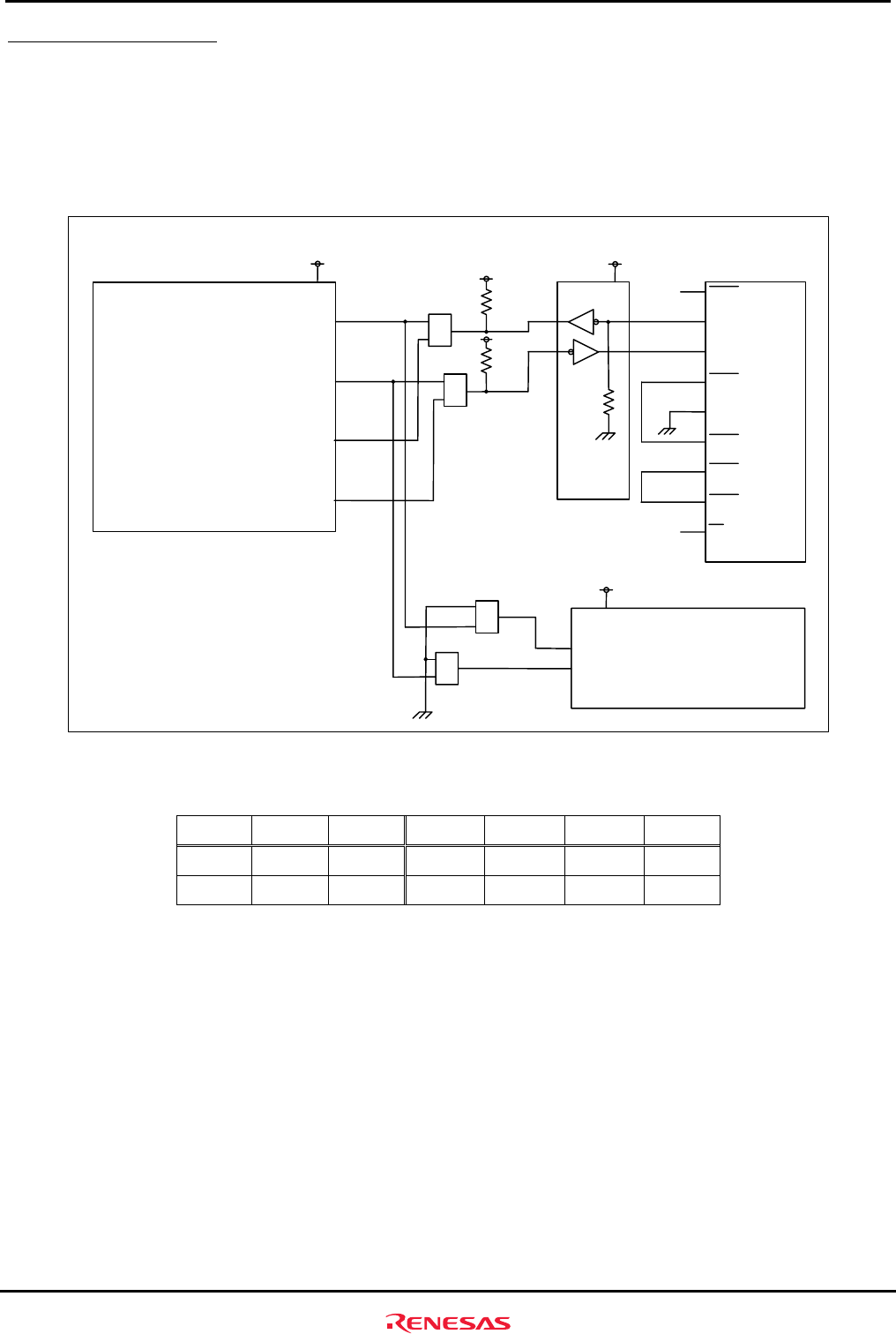
SH7137 SCI0 or SCI 1 pins can be connected to the serial port connector on the M3A-HS37 (default: PE1 pin and PE2 pin are
connected to the serial port connector, J3). The serial port switch jumpers (JP7, JP8, JP9, and JP10) switch the SCI channels
connected to a serial port connector.
Figure 2.4.1 shows the serial port block diagram on the M3A-HS37, and Table 2.4.1 lists the jumper connections.
SH7137
DCD
RxD
TxD
DTR
GND
DSR
RTS
CTS
RI
1
2
3
4
5
6
7
8
9
NC
NC
Serial port
connector
RS-232C
driver
PA3/RXD1/A3/IRQ1
PA4/TXD1/A4/IRQ2
PE1/TIOC0B/RXD0
PE2/TIOC0C/TXD0
1
2
3
JP8
1
2
3
JP7
A3
A4
1
2
3
JP9
1
2
3
JP10
SRAM
CPU-VCC
CPU-VCC
4.7 K
4.7 K
CPU-VCC
CPU-VCC
CPU-VCC
(M5M5256DFP-70GI)
CPU-VCC:3.3 V/ 5 V
Figure 2.4.1 Serial Port Block Diagram
Table 2.4.1 Jumper Connections
SCI0 SCI1 SRAM JP7 JP8 JP9 JP10
Y N Y 2-3 2-3 2-3 2-3
N Y N 1-2 1-2 1-2 1-2
Note: Y = yes, N = no


